


CASE 5600 series
User Manual
17
© 2004-2006 Rosewill Inc. All rights reserved by Rosewill
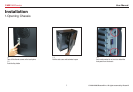
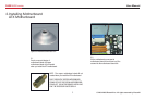
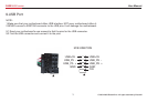
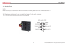
12.System Control Connectors
1. Read your motherboard’s user manual to find the pins for these system control connectors.
2. Refer to your motherboard’s user manual to connect these connectors correctly.
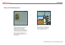
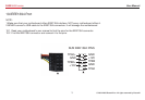
PLED+
PLED-
IDE_LED+
IDE_LED-
PWA
Ground
Reset
Ground
Ground
Ground
Speaker
+5V
PLED
PWR
RESETIDE_LED
SPEAKER
System Warning Speaker
ATTENTION :
The diagram is just an example.
NOT every motherboard has the same
layout of these system control pins.
Please refer to your motherboard
user’s manual to check the layout
before the installation.
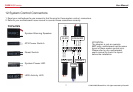
Connectors
ATX Power Switch
Reset Switch
System Power LED
HDD Activity LED