


GS-2124C User Manual
Publication date: June, 2005
Revision A1
10
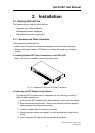
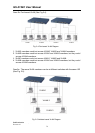
• TP Port and Cable Installation
⇒ In the switch, TP port supports MDI/MDI-X auto-crossover, so both types of
cable, straight-through (Cable pin-outs for RJ-45 jack 1, 2, 3, 6 to 1, 2, 3, 6 in
10/100M TP; 1, 2, 3, 4, 5, 6, 7, 8 to 1, 2, 3, 4, 5, 6, 7, 8 in Gigabit TP) and
crossed-over (Cable pin-outs for RJ-45 jack 1, 2, 3, 6 to 3, 6, 1, 2) can be used.
It means you do not have to tell from them, just plug it.
⇒ Use Cat. 5 grade RJ-45 TP cable to connect to a TP port of the switch and the
other end is connected to a network-aware device such as a workstation or a
server.
⇒ Repeat the above steps, as needed, for each RJ-45 port to be connected to a
Gigabit 10/100/1000 TP device.
Now, you can start having the switch in operation.
•
••
•
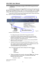
Power On
The switch supports 100-240 VAC, 50-60 Hz power supply. The power
supply will automatically convert the local AC power source to DC power. It does not
matter whether any connection plugged into the switch or not when power on, even
modules as well. After the power is on, all LED indicators will light up immediately
and then all off except the power LED still keeps on. This represents a reset of the
system.
•
••
•
Firmware Loading
After resetting, the bootloader will load the firmware into the memory. It will
take about 30 seconds, after that, the switch will flash all the LED once and
automatically performs self-test and is in ready state.
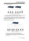
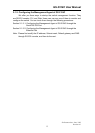
2-1-2. Cabling Requirements
To help ensure a successful installation and keep the network performance
good, please take a care on the cabling requirement. Cables with worse
specification will render the LAN to work poorly.