


GS-2124C User Manual
Publication date: June, 2005
Revision A1
16
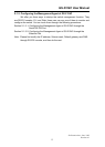
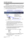
2-1-3-1. Configuring the Management Agent of GS-2124C through the Serial
RS-232 Port
To perform the configuration through RS-232 console port, the switch’s serial
port must be directly connected to a DCE device, for example, a PC, through
RS-232 cable with DB-9 connector. Next, run a terminal emulator with the default
setting of the switch’s serial port. With this, you can communicate with the switch.
In the switch, RS-232 interface only supports baud rate 57.6k bps with 8 data
bits, 1 stop bit, no parity check and no flow control.
To configure the switch, please follow the procedures below:
1. Find the RS-232 DB-9 cable with female DB-9 connector bundled.
Normally, it just uses pins 2, 3 and 7. See also Appendix B for more
details on Null Modem Cable Specifications.
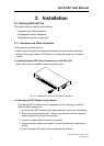
2. Attaches the DB-9 female cable connector to the male serial RS-232
DB-9 connector on the switch.
3. Attaches the other end of the serial RS-232 DB-9 cable to PC’s serial
port, running a terminal emulator supporting VT100/ANSI terminal with
The switch’s serial port default settings. For example,
Windows98/2000/XP HyperTerminal utility.
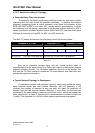
Note: The switch’s serial port default settings are listed as follows:
Baud rate 57600
Stop bits 1
Data bits 8
Parity N
Flow control none
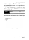
4. When you complete the connection, then press <Enter> key. The login
prompt will be shown on the screen. The default username and
password are shown as below:
Username = admin Password = admin
24 Gigabit L2 Managed Switch
Default IP Setting:
IP address = 192.168.1.1
Subnet Mask = 255.255.255.0
Default Gateway = 192.168.1.254
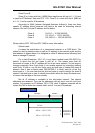
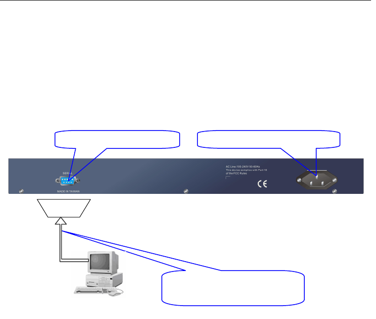
Terminal or Terminal Emulator
Fig. 2-6
RS-232 cable with female
DB-9 connector at both ends
RS-232
AC Line 100
-
240V 50/60 Hz
RS
-
232 DB
-
9 Connec
tor