


3. Installation
RuggedCom® RuggedBackbone™ 22 RX5000 Installation Guide Rev106
3.2. Power Supply Wiring And Grounding
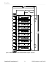
The RuggedBackbone™ RX5000 may be ordered with dual redundant power supplies, in positions
PM1 and PM2 (see Figure 2.1, “Chassis Slot Assignment”). Power connections are located either on
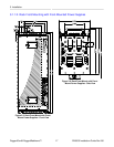
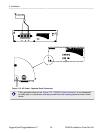
the PM1 and PM2 module face plates or on the front panel of the RX5000. An optional chassis ground
connection is located on the front panel as pictured in AC Power - Separate Earth Connection.
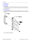
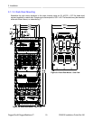
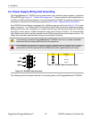
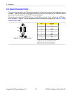
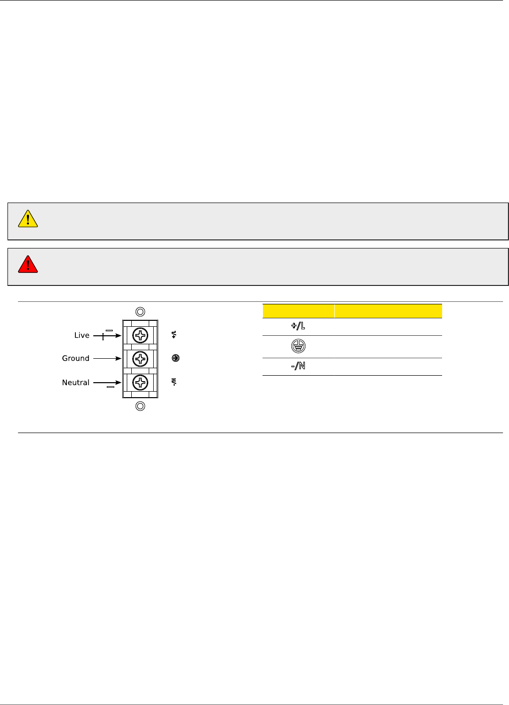
Each RX5000 Power Module is equipped with a Phillips screw terminal block (Figure 3.12) for main
power connection. The Phillips Screw Terminal Block has Phillips screws with compression plates,
allowing either bare wire connections or crimped terminal lugs. We recommend the use of #6 size
ring lugs to ensure secure, reliable connections under severe shock or vibration. The terminal block
has a safety cover which must be removed via two Phillips screws before connecting any wires. The
safety cover must be reattached after wiring to ensure personnel safety.
A permanently connected RuggedBackbone™ RX5000 must have a readily accessible
disconnect device incorporated external to the equipment.
The RX5000 may have two (2) power supplies installed and be supplied from multiple
power sources. Service personnel must isolate both power supplies prior to servicing.
Figure 3.12. RX5000 Power Connector
Pin Function
Live
Ground
Neutral
Table 3.1. RX5000 Power Connector Pinout
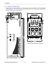
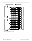
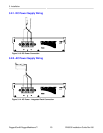
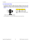
The following sections illustrate methods of connecting power to the RuggedBackbone™ RX5000.