


2. RuggedBackbone™ Modules
RuggedCom® RuggedBackbone™ 9 RX5000 Installation Guide Rev106
2. RuggedBackbone™ Modules
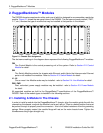
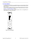
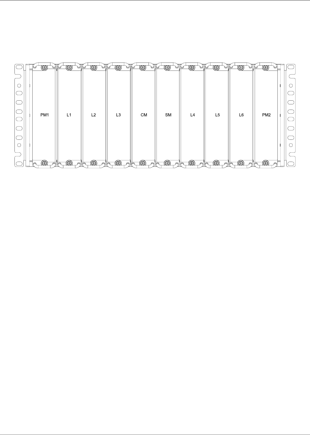
The RX5000 chassis comprises ten slots, each one of which is designed to accommodate a particular
module. Figure 2.1 shows the rear panel view of the RX5000. The slot name at each position (“PM1”,
“L1”, etc.) denotes the type of module that may be installed at that position in the chassis.
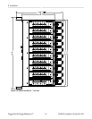
Figure 2.1. Chassis Slot Assignment
The slot name markings in the diagram above represent the following RuggedBackbone™ modules:
CM
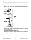
The Control Module is the central processing unit of the system. Refer to Section 2.2: Control
Module for detail.
SM
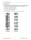
The Switch Module contains the chassis-wide Ethernet switch fabric that interconnects Ethernet
ports on all installed line modules. Refer to Section 2.3: Switch Module for detail.
L1..L6
One or more Line Module cards may be installed - refer to Section 2.4: Line Modules for detail.
PM1, PM2
Dual, redundant, power supply modules may be installed - refer to Section 2.5: Power Module
for detail.
All supported modules are built to the RuggedRated™ specifications of the RuggedBackbone™
RX5000. Each of the module types is detailed in the following sections.
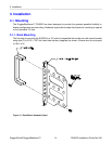
2.1. Installing A Module In The Chassis
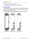
In order to install a module into the RuggedBackbone™ chassis, align the module guide ribs with the
channels on the chassis, and push the module in as far as it will go. There is a detent position that must
be pushed through to properly seat the connectors - this is the added resistance from the grounding
springs. When properly seated, the module flange will rest on the main chassis frame. Tighten the
thumbscrews using finger strength only.