


LCD CONTROLLER/DRIVER KS57C2308/P2308/C2316/P2316
12-6
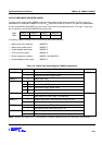
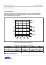
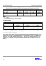
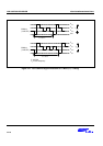
Table 12-5. LCD Clock Signal (LCDCK), Frame Frequency and LCD sync Signal (LCDSY)
LCDCK frequency Static 1/2 Duty 1/3 Duty 1/4 Duty
fw/2
9
= 64 Hz
64 (16) 32 (16) 21 (21) 16 (16)
fw/2
8 =
128 Hz
128 (32) 64 (32) 43 (43) 32 (32)
fw/2
7
= 256 Hz
256 (64) 128 (64) 85 (85) 64 (64)
fw/2
6
= 512 Hz
512 (128) 256 (128) 171 (171) 128 (128)
NOTES:
1. fw = 32.768 kHz
2. The number in parentheses is a frequency for LCDSY.
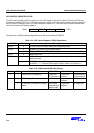
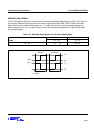
LCD DRIVE VOLTAGE
LCD Power Supply Static Mode 1/2 Bias 1/3 Bias
V
LC0
V
LCD
V
LCD
V
LCD
V
LC1
2/3 V
LCD
1/2 V
LCD
2/3 V
LCD
V
LC2
1/3 V
LCD
1/2 V
LCD
1/3 V
LCD
GND 0 V 0 V 0 V
NOTE: The LCD panel display may deteriorate if DC voltage is applied between the common and segment signals.
Therefore, always drive the LCD panel with AC voltage.
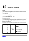
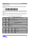
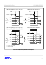
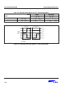
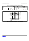
LCD VOLTAGE DIVIDING RESISTORS
On-chip voltage dividing resistors for the LCD drive power supply can be configured by internal voltage dividing
resistors. Using these internal voltage dividing resistors, you can drive either a 3 V or a 5 V LCD display using
external bias. Bias pins are connected externally to the V
LCD
pin so that it can handle the different LCD drive
voltages. To cut off the current supply to the voltage dividing resistors, clear LCON.0 when you turn the LCD
display off.