


PRODUCT OVERVIEW KS57C2308/P2308/C2316/P2316
1-6
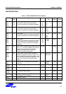
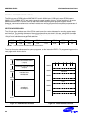
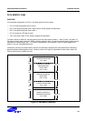
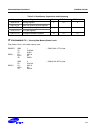
Table 1-1. KS57C2308/C2316 Pin Descriptions (Continued)
Pin Name Pin
Type
Description Number Share
Pin
Reset
Value
Circuit
Type
LCDSY I/O LCD synchronization clock output for LCD
display expansion
33 P3.1 Input D
TCL0 I/O External clock input for timer/counter 0 27 P1.3 Input A-1
TCLO0 I/O Timer/counter 0 clock output 28 P2.0 Input D
SI I Serial interface data input 23 P0.3 Input A-1
SO I/O Serial interface data output 22 P0.2 Input
D
*
SCK
I/O Serial I/O interface clock signal 21 P0.1 Input
D
*
INT0
INT1
I External interrupts. The triggering edge for
INT0 and INT1 is selectable. Only INT0 is
synchronized with the system clock.
24
25
P1.0
P1.1
Input A-1
INT2 I Quasi-interrupt with detection of rising edge
signals.
26 P1.2 Input A-1
INT4 I External interrupt input with detection of rising
or falling edge
20 P0.0 Input A-1
KS0–KS7 I/O Quasi-interrupt inputs with falling edge
detection.
44–51 P6.0–P7.3 Input
D
*
CLO I/O CPU clock output 30 P2.2 Input D
BUZ I/O 2, 4, 8 or 16 kHz frequency output for buzzer
sound with 4.19 MHz main system clock or
32.768 kHz subsystem clock.
31 P2.3 Input D
X
IN,
X
OUT
– Crystal, ceramic or RC oscillator pins for main
system clock. (For external clock input, use
X
IN
and input X
IN
‘s reverse phase to X
OUT
)
15,14 – – –
XT
IN,
XT
OUT
– Crystal oscillator pins for subsystem clock.
(For external clock input, use XT
IN
and input
XT
IN
's reverse phase to XT
OUT
)
17,18 – – –
V
DD
– Main power supply 12 – – –
V
SS
– Ground 13 – – –
RESET
– Reset signal 19 – Input B
TEST –
Test signal input (must be connected to V
SS
)
16 – – –
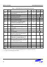
NOTES:
1. Pull-up resistors for all I/O ports are automatically disabled if they are configured to output mode.
2. D
*
Type has a schmitt trigger circuit at input.