


Spinpoint M8U-Internal Product Manual REV 3.4
28
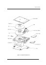
INSTALLATION
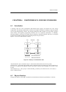
5.3 Servo System
The Servo System controls the position of the read/write heads and holds them on track during read/write
operations. The Servo System also compensates for MR write/read offsets and thermal offsets between
heads on different surfaces and for vibration and shock applied to the drive.
The Spinpoint M8U hard disk drive is an Embedded Sector Servo System. Positioning information is
radically located in evenly spaced servo sectors on each track.
Radial position information can be provided from these sectors for each data head. Because the drive
incorporates multiple data zones and each zone has a different bit density, split data fields are necessary for
optimal use of the non-servo area of the disk. The servo area remains phase-coherent across the surface of
the disk, even though the disk has various data zones. The main advantage of the Embedded Sector Servo
System is that it eliminates the problems of static and dynamic offsets between heads on different surfaces.
The Spinpoint M8U hard disk drive Servo System is classified as a digital servo syste
m because track-
following and seek control, bias cancellation, and other typical tasks are done in a Digital Signal Processor
(DSP).
The Servo system has three modes of operation: track-following mode, settle mode, and velocity control
mode.
1. Track-following mode is used when heads are “on-track.” This is a position loop with an
integrator in the compensation.
2. Settle mode is used for all accesses; head switches, short-track seeks and long-track seeks.
Settle mode is a position loop with velocity damping. Settle mode does not use feed forward.
3. Velocity control mode is used for acceleration and deceleration of the actuator for seeking of
two or more tracks. A seek operation of this length is accomplished with a velocity control
loop. The drive’s ROM stores the velocity profile in a look-up table.
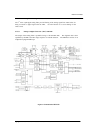
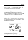
5.4 Read and Write Operations
The following two sections describe the read and write channels.
5.4.1 The Read Channel
The drive has one read/write head for each of the data surfaces. The signal path for the Read Channel starts
at the read/write heads. When the magnetic flux transitions recorded on a disk pass under the head, they
generate low-amplitude, differential output voltages. The read/write head transfers these signals to the
flexible circuit’s amplifier, which amplifies the signal.
The flexible circuit transmits the pre-amplified signal from the HDA to the PCBA. The EPRML channel on
the PCBA shapes, filters, detects, synchronizes, and decodes the data from the disk. The Read/Write IC
then sends the resynchronized data output to the 88i9322 (Rev2.0) DSP & Interface/Disk Controller.
The 88i9322(Rev2.0) Disk Controller manages the flow of data between the Data Synchronizer on the
Read/Write IC and its AT Interface Controller. It also controls data access for the external RAM buffer.