


Spinpoint M8U-Internal Product Manual REV 3.4
40
INSTALLATION
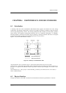
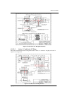
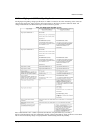
Cable assembly that violates USB topology rules
A cable assembly with both ends terminated in either Series “A” plugs or Series “B” receptacles.
This allows two downstream ports to be directly connected.
Note: This prohibition does not prevent using a USB device to provide a bridge between two USB
buses.
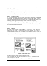
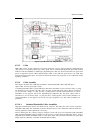
Standard detachable cables for low-speed devices
Low-speed devices are prohibited from using standard detachable cables. A standard detachable
cable assembly must be high-/full-speed. Since a standard detachable cable assembly is high-/fullspeed
rated, using a long high-/full-speed cable exceeds the capacitive load of low-speed.
6.2.2 Electrical Interface
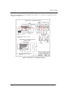
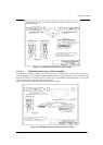
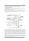
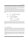
The USB transfers signal and power over a four-wire cable, shown in Figure 6-10. The signaling occurs over
two wires on each point-to-point segment.
There are three data rates:
The USB high-speed signaling bit rate is 480 Mb/s.
The USB full-speed signaling bit rate is 12 Mb/s.
A limited capability low-speed signaling mode is also defined at 1.5 Mb/s.
USB 2.0 host controllers and hubs provide capabilities so that full-speed and low-speed data can be
transmitted at high-speed between the host controller and the hub, but transmitted between the hub and the
device at full-speed or low-speed. This capability minimizes the impact that full-speed and low-speed
devices have upon the bandwidth available for high-speed devices.
The low-speed mode is defined to support a limited number of low-bandwidth devices, such as mice,
because more general use would degrade bus utilization.
The clock is transmitted, encoded along with the differential data. The clock encoding scheme is NRZI
with bit stuffing to ensure adequate transitions. A SYNC field precedes each packet to allow the receiver(s)
to synchronize their bit recovery clocks.
The cable also carries VBUS and GND wires on each segment to deliver power to devices. VBUS is nominally
+5 V at the source. The USB allows cable segments of variable lengths, up to several meters, by choosing
the appropriate conductor gauge to match the specified IR drop and other attributes such as device power
budget and cable flexibility. In order to provide guaranteed input voltage levels and proper termination
impedance, biased terminations are used at each end of the cable. The terminations also permit the detection
of attach and detach at each port and differentiate between high/full-speed and low-speed devices.
Figure 6-10: USB Cable Signal
6.2.2.1 Electrical Overview
This chapter describes the electrical specification for the USB. It contains signaling, power distribution, and
physical layer specifications. This specification does not address regulatory compliance. It is the
responsibility of product designers to make sure that their designs comply with all applicable regulatory
requirements.
The USB 2.0 specification requires hubs to support high-speed mode. USB 2.0 devices are not required to
support high-speed mode. A high-speed capable upstream facing transceiver must not support low-speed
signaling mode. A USB 2.0 downstream facing transceiver must support high-speed, full-speed, and low-
speed modes.
To assure reliable operation at high-speed data rates, this specification requires the use of cables that conform
to all current cable specifications.
In this chapter, there are numerous references to strings of J’s and K’s, or to strings of 1’s and 0’s. In each of
these instances, the leftmost symbol is transmitted/received first, and the rightmost is transmitted/received
last.