


Spinpoint M8U-Internal Product Manual REV 3.4
47
INSTALLATION
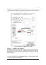
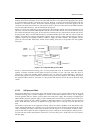
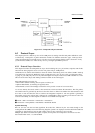
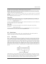
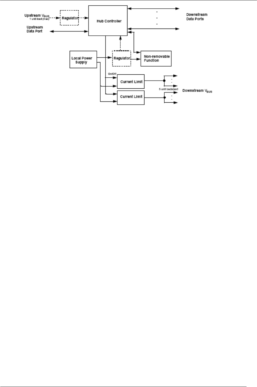
Figure 6-13: Compound Self-powered Hub
6.3 Protocol Layer
This chapter presents a bottom-up view of the USB protocol, starting with field and packet definitions. This
is followed by a description of packet transaction formats for different transaction types. Link layer flow
control and transaction level fault recovery are then covered. The chapter finishes with a discussion of retry
synchronization, babble, loss of bus activity recovery, and high-speed PING protocol.
6.3.1 Protocol Layer Overview
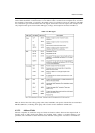
This chapter describes the USB packets at a byte level including the sync, pid, address, endpoint, CRC fields.
Once this has been grasped it moves on to the next protocol layer, USB packets.
Unlike RS-232 or similar serial interfaces where the format of data being sent is not defined, USB is made up
of several layers of protocols. While this sounds complicated, don’t give up now. Once you understand what
is going on, you really only have to worry about the higher level layers. In fact most USB controller I.C.s will
take care of the lower layer, thus making it almost invisible to the end designer.
Each USB transaction consists of a
• Token Packet (Header defining what it expects to follow), an
• Optional Data Packet, (Containing the payload) and a
• Status Packet (Used to acknowledge transactions and to provide a means of error correction)
As we have already discussed, USB is a host centric bus. The host initiates all transactions. The first packet,
also called a token is generated by the host to describe what is to follow and whether the data transaction will
be a read or write and what the device’s address and designated endpoint is. The next packet is generally a
data packet carrying the payload and is followed by a handshaking packet, reporting if the data or token was
received successfully, or if the endpoint is stalled or not available to accept data.
■ Frame = SOF + Transaction + Transaction + Transaction
■ Transaction = Setup Packet + Data Packet + Handshake Packet
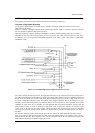
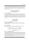
Byte/Bit Ordering
Bits are sent out onto the bus least-significant bit (LSb) first, followed by the next LSb, through to the
mostsignificant bit (MSb) last. In the following diagrams, packets are displayed such that both individual bits
and fields are represented (in a left to right reading order) as they would move across the bus.
Multiple byte fields in standard descriptors, requests, and responses are interpreted as and moved over the
bus in little-endian order, i.e., LSB to MSB.