


Section 3: Configuration and Operation
SATO D508/D512 Operator Manual Page 3-3
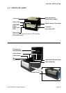
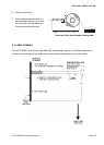
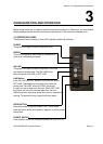
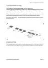
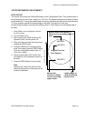
3.3 THE CONFIGURATION PANEL
The Configuration Panel is accessible when you lift up the top cover.
The panel consists of an eight-position DIP switch, four adjustment potentiometers and a seven-
segment LED Error Status display. Receptacles for connecting the optional Cutter (factory
installed) are also located on this panel.
Change and fine-tune your printer settings as required by using the mini-screw driver to turn the
potentiometers clockwise/anti-clockwise until you have the optimal adjustment position.
Do not touch VR2 and VR3. They are reserved for professional adjustments and for a trained
service person only.
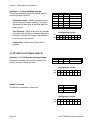
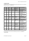
DIP SWITCH SETTINGS
This is an eight-position switch used for setting the operating conditions of the printer. Switches 1
to 3 act as control for both paper handling and the loading of programs or fonts into the printer.
Paper handling
Reserved
Head Check
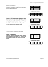
VR1 adjust
DATA Dump
Reserved
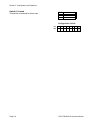
Error
Status
LED
DIP switch for
Conguration
VR4
Label Pitch
Oset
VR2
VR3
VR1
Oset or
Darkness