


184 SATO RISC Printers
5. Interface Specifications Programming Manual
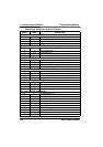
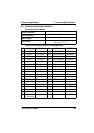
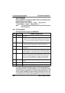
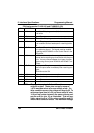
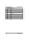
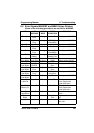
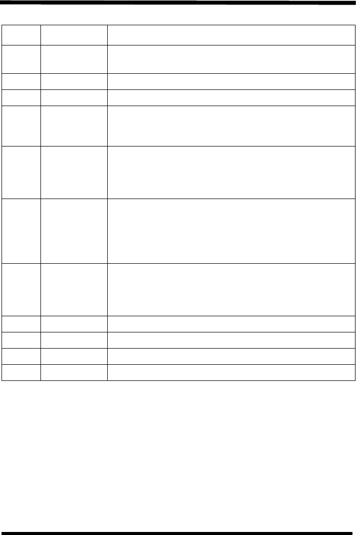
PIN Assignments CL 408/412 and CL608/612 (VA)
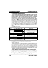
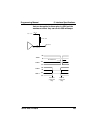
NOTE: The signals on pins 1, 3 4 and 6 each have an open
collector output. These pins normally measure
+.07V maximum when a true condition exists. If a
false condition occurs, the voltage will drop to 0V. To
achieve a signal level of +5V, you must add a 1K ohm,
¼ W pull-up resistor between the open collector out-
put pin and Vcc (pin 13) as illustrated. This will pro-
vide a signal level of +5V for a true condition and 0V
when a false condition exists. The maximum voltage
PIN DIRECTION SIGNAL DESCRIPTION
1 To Host Label Out - This pin goes low (0V) when a label out
error exists.
2 Reference Signal Ground
3 To Host Ribbon Out - This pin goes low when the ribbon is out.
4 To Host Error - This pin goes low when the printer detects an
error condition such as head open or receiving buffer
full.
5 To Printer Print Start - The printer will print one label when this
pin is pulled to ground. This signal must be enabled
by placing switch DSW3-5 on the Control Panel in the
ON position.
6 To Host End Print - It is used to drive an applicator or other
external device requiring synchronization with the print
cycle. You may choose between four types of output
signals using control panel DSW3-6 and DSW3-7 sel-
ections.
7 To Printer Print Repeat - The printer repeatedly prints the current
label in the print buffer immediately after receiving this
signal.
DSW3-8 must be ON.
10 To Host +12V - Used to power accessory items.
12 To Host +24V - Used to power accessory items.
13 To Host Vcc - +5V
14 Reference Frame Ground