


10 31005009 01 November 2003
Field Wiring Guidelines
Overview This section contains wiring guidelines and precautions for wiring the
170AMM11030 Momentum I/O base.
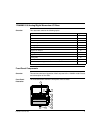
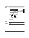
Terminal
Connector
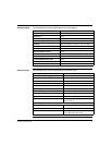
To connect field devices to the I/O base, you need a field wiring terminal connector.
Schneider Electric sells terminal connectors in sets of three.
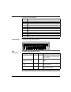
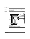
Busbar May Be
Required
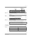
Depending on the type of field devices you are using, you may need a 1-, 2-, or 3-
row busbar. The following busbars are available from Schneider Electric.
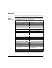
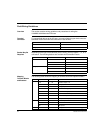
Mapping
Terminal Blocks
and Busbars
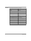
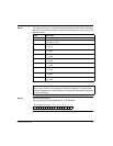
The following table shows the mapping of terminal blocks and optional busbars.
Type Part Number
Screw-in 170 XTS 001 00
Spring-clip 170 XTS 002 00
Type Number of Rows Part Number
Screw-in 1 - row 170 XTS 006 01
2 - row 170 XTS 005 01
3 - row 170 XTS 004 01
Spring-clip 1 - row 170 XTS 007 01
2 - row 170 XTS 008 01
3 - row 170 XTS 003 01
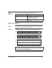
Row # Terminal # Connection Function
2 1-8 01 ... 08 Discrete outputs 1-8
9-10 AI1, AI2 Analog inputs 1-2
11 & 13 AO1+, AO2+ Analog outputs 1-2
12 & 14 AO1-, AO2- Return for analog outputs 1-2
15 AGND Return for analog inputs
16 Return for discrete outputs
17 Return for outputs
18 +DC power for outputs
3 1-16 I1 ... I16 Discrete inputs 1-16
17 Return
18 +DC power
4 1-18 PE Earth ground for field devices, PE analog ground