


14 31005009 01 November 2003
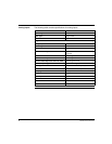
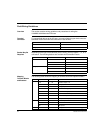
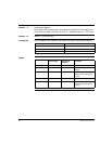
Word 1 System Info Register
This word enables the module’s operation, and specifies if user shutdown values are
expected.
Valid setting for word one are 0001 ... FFFF
The module’s default value at power-up for this register is zero
(module shut down).
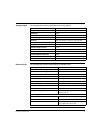
Word 2 Discrete Fail State Reaction and Value Register
This word combines the value and reaction in a fail state.
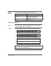
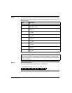
Word 3 Analog Fail State Reaction Register
This word contains two 2 bit fields that define the fail state for each channel. The four
possible values of fail state are as follows.
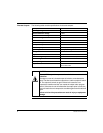
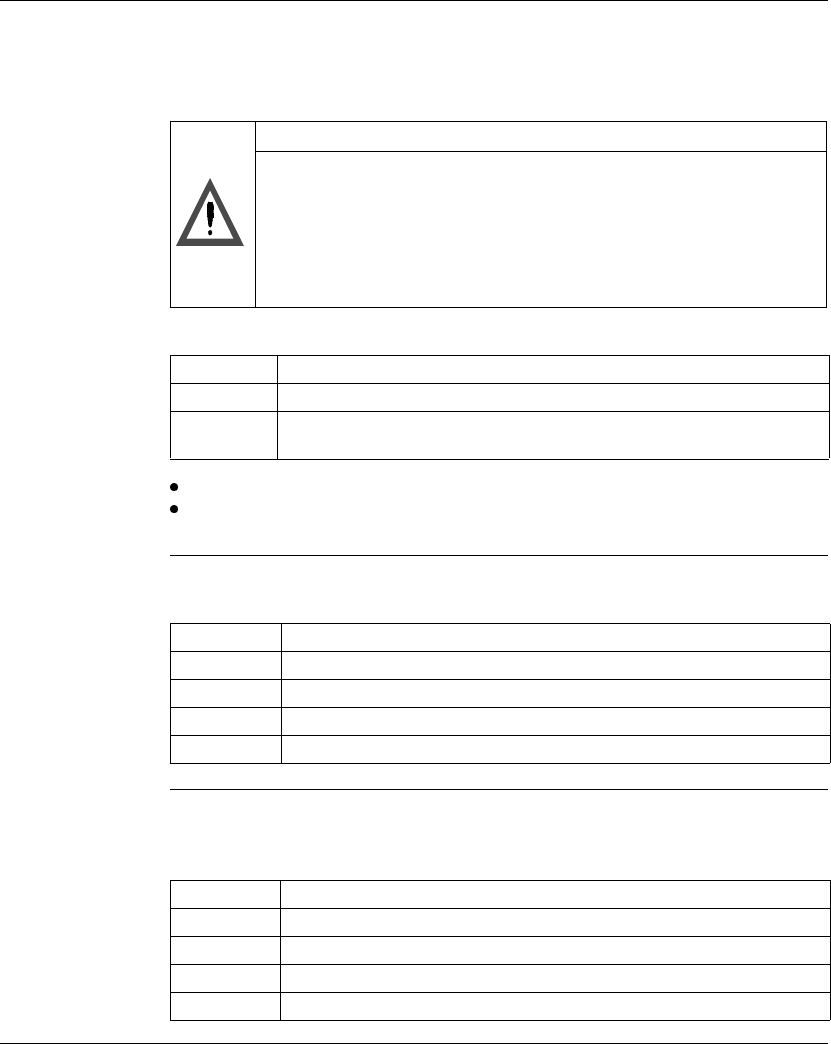
CAUTION
Zero is an illegal value for the parameter field (words 1-5).
A zero value in the parameter field will cause an output shut down state,
and no inputs or outputs are updated. Any bit set in the parameter field,
including those defined as not used, will enable the module.
Failure to follow this precaution can result in injury or equipment
damage.
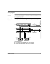
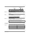
Word 1 Description
Bits 0 ... 14 Not used
Bit 15 0 = Disables user defined shutdown values.
1 = Enables user defined shutdown values.
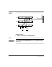
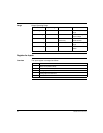
Word 2 Description
Bit 0 ... 7 Discrete fail state value for outputs 1 ... 8
Bits 8 ... 13 Not used
Bit 14 0 = hold last value, 1 = user defined value
Bit 15 0 = all outputs reset, 1 = check bit 14
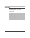
2 Bit Value Fail State
00 Minimum output voltage
01 Hold last value (default)
10 User defined shutdown value
11 Hold last value (not normally used)