


4 31005009 01 November 2003
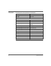
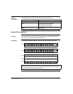
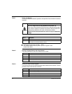
Components of the I/O Module:
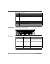
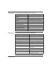
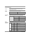
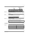
LED Illustration The illustration below shows the LEDs.
LED
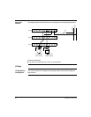
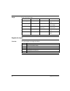
Descriptions
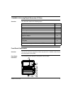
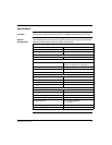
The following table describes the LEDs.
Label Description
1 Internal interface (ATI) connector
2 Locking and ground contact for the adapter
3 LED status display
4 Protective cover
5 Sockets for the terminal connectors
6 Grounding screw
7 Busbar mounting slot
8 Locking tab for DIN rail mount
9 Mounting holes for panel mount
10 Standoff -- ground nut
IN
OUT
OUT
ready
LED Color Status Meaning
Ready Green ON I/O base is communicating with the
comm adapter/CPU top hat. CPU must
be in RUN state.
I1, I2, I3, I4, I5, I6, I7, I8,
I9, I10, I11, I12, I13, I14,
I15, I16
Green ON Indicates the corresponding input point
is ON.
O1, O2, O3, O4, O5, O6,
O7, O8
Green ON Indicates the corresponding discrete
output point is ON.
AO1, AO2 Green ON Indicates the corresponding analog
output channel is active.