


930-112-01 PowerLogic
TM
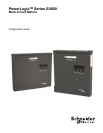
E4800 Series
02/2009 PowerLogic E4800 configuration tool guide
© 2009 Schneider Electric All Rights Reserved
1
POWERLOGIC E4800
CONFIGURATION TOOL GUIDE
This document describes how to configure the the PowerLogic E4800 meter
(PowerLogic E4833, E4880 and E4805 meters), using the PowerLogic
configuration tool. It includes the following configuration tool information:
• “System Set-up and Description” on page 1
• “Configuration and Programming” on page 1
• “Display Navigation” on page 4
• “PowerLogic Configuration Tool” on page 7
• “Communications Connections” on page 5
• “Configuring the meter” on page 7
• “Manufacturing Tab” on page 16
• “Meter Points (Circuits) Tab” on page 17
• “Pulse Probes Tab” on page 20
• “Completing the Meter Configuration” on page 21
This documentation is intended for those responsible for configuring the
PowerLogic E4833, E4880 and E4805 meters.
System Set-up and Description The configuration tool supports the PowerLogic E4833, E4880 and E4805
meters.
Depending on how the meters are installed and configured, they can meter
8, 12, or 24 individual meter points. The PowerLogic E4833, E4880 and
E4805 meters are designed for residential, commercial, and industrial use
and display the power and consumption readings for each measurement
point.
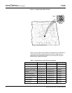
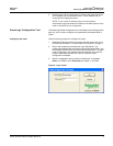
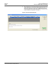
Configuration and Programming The configuration tool is used to change any of the programmable
parameters within the PowerLogic E4800 meters. The combination of the
configuration tool and the state of the meter programming switches
determine which parameters can be changed. As shown in Figure ?, the
programming switches are two-position DIP switches labeled SW1, and are
located inside the meter cover below the Display button. To enable meter
configuration, both switches must be physically set to the ON (down) position
(default).