


Seagate Enterprise Capacity 2.5 HDD v3 SAS Product Manual, Rev. D 39
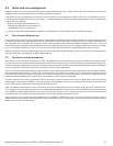
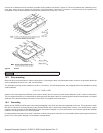
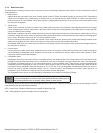
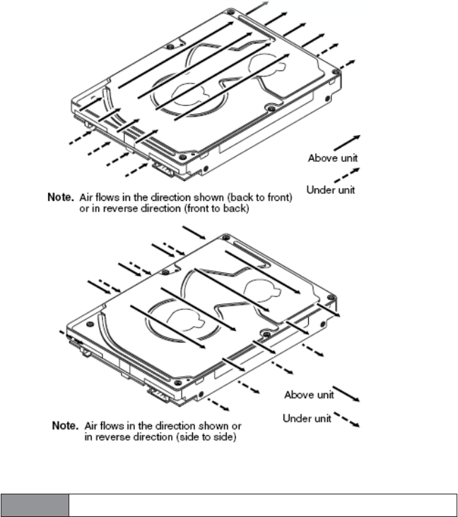
If forced air is determined to be necessary, possible air-flow patterns are shown in Figure 9. The air-flow patterns are created by one or
more fans, either forcing or drawing air as shown in the illustrations. Conduction, convection, or other forced air-flow patterns are
acceptable as long as the temperature measurement guidelines of Section 6.5.1 are met.
Figure 9. Air flow
.
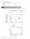
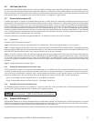
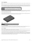
10.3 Drive mounting
Mount the drive using the bottom or side mounting holes. If mounting the drive using the bottom holes, ensure to not physically distort the
drive by attempting to mount it on a stiff, non-flat surface.
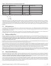
The allowable mounting surface stiffness is 80 lb/in (14.0 N/mm). The following equation and paragraph define the allowable mounting
surface stiffness:
where K is the mounting surface stiffness (units in lb/in or N/mm) and X is the out-of-plane surface distortion (units in inches or millimeters).
The out-of-plane distortion (X) is determined by defining a plane with three of the four mounting points fixed and evaluating the out-of-plane
deflection of the fourth mounting point when a known force (F) is applied to the fourth point.
10.4 Grounding
Signal ground (PCBA) and HDA ground are connected together in the drive and cannot be separated by the user. The equipment in which
the drive is mounted is connected directly to the HDA and PCBA with no electrically isolating shock mounts. If it is desired for the system
chassis to not be connected to the HDA/PCBA ground, the systems integrator or user must provide a nonconductive (electrically isolating)
method of mounting the drive in the host equipment.
Increased radiated emissions may result if maximum surface area ground connection is not provided between system ground and drive
ground. This is the system designer’s and integrator’s responsibility.
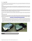
Note
Image is for reference only, may not represent actual drive.
K x X = F < 15lb = 67N