


Seagate Enterprise Capacity 2.5 HDD v3 SAS Product Manual, Rev. D 54
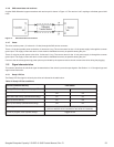
The Ready LED Out signal is designed to pull down the cathode of an LED. The anode is attached to the proper +3.3 volt supply through
an appropriate current limiting resistor. The LED and the current limiting resistor are external to the drive. See the next table for the output
characteristics of the LED drive signals.
11.5.2 Differential signals
The drive SAS differential signals comply with the intra-enclosure (internal connector) requirements of the SAS standard.
The table below defines the general interface characteristics
11.6 SAS-3 Specification compliance
Seagate SAS-3 compatible drives are compliant with the latest SAS-3 Specification (T10/BSR INCITS 519 rev. 06).
The main difference from SAS-2 is the Tx and Rx training that allows the host and drive to adjust the amplitude and emphasis values to the
channel. The receiver still employs Decision Feedback Equalizer (DFE) and Feed Forward Equalizer (FFE) circuitry to accomplish this
training.
11.7 Additional information
Please contact the Seagate representative for SAS electrical details, if required.
For more information about the Phy, Link, Transport, and Applications layers of the SAS interface, refer to the Seagate SAS Interface
Manual, part number 100293071.
For more information about the SCSI commands used by Seagate SAS drives, refer to the Seagate SCSI Commands Reference Manual,
part number 100293068.
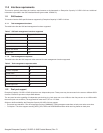
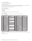
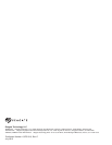
Table 13 LED drive signal
State Test condition Output voltage
LED off, high 0 V £ VOH £ 3.6 V -100 μA < I
OH
< 100 μA
LED on, low I
OL
= 15 mA 0 £ V
OL
£ 0.225 V
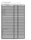
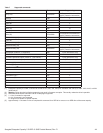
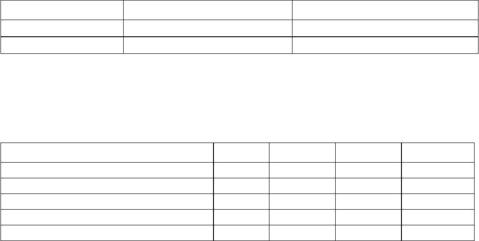
Table 14 General interface characteristics
Characteristic Units 3.0Gb/s 6.0Gb/s 12.0Gb/s
Bit rate (nominal) Mbaud 3,000 6,000 12,000
Unit interval (UI)(nominal) ps 333.3 166.6 83.3
Impedance (nominal, differential ) ohm 100 100 100
Transmitter transients, maximum V ± 1.2 ± 1.2 ± 1.2
Receiver transients, maximum V ± 1.2 ± 1.2 ± 1.2