


CONSTELLATION ES.3 SERIAL ATA PRODUCT MANUAL, REV. A 33
6.0 SERIAL ATA (SATA) INTERFACE
These drives use the industry-standard Serial ATA interface that supports FIS data transfers. It supports ATA programmed input/output
(PIO) modes 0–4; multiword DMA modes 0–2, and Ultra DMA modes 0–6.
For detailed information about the Serial ATA interface, refer to the “Serial ATA: High Speed Serialized AT Attachment” specification.
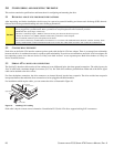
6.1 HOT-PLUG COMPATIBILITY
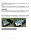
Constellation ES.3 Serial ATA drives incorporate connectors which enable you to hot plug these drives in accordance with the Serial ATA
Revision 2.6 specification. This specification can be downloaded from www.serialata.org.
Caution:
The drive motor must come to a complete stop (Ready to spindle stop time indicated in Section 2.5)
prior to changing the plane of operation. This time is required to insure data integrity.
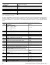
6.2 SERIAL ATA DEVICE PLUG CONNECTOR PIN DEFINITIONS
Table 8 summarizes the signals on the Serial ATA interface and power connectors.
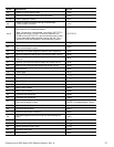
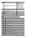
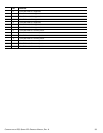
Table 8 Serial ATA connector pin definitions
SEGMENT PIN FUNCTION DEFINITION
Signal
S1 Ground 2nd mate
S2 A+ Differential signal pair A from Phy
S3 A-
S4 Ground 2nd mate
S5 B- Differential signal pair B from Phy
S6 B+
S7 Ground 2nd mate
Key and spacing separate signal and power segments
Power
P1 V
33
3.3V power
P2 V
33
3.3V power
P3 V
33
3.3V power, pre-charge, 2nd mate
P4 Ground 1st mate
P5 Ground 2nd mate
P6 Ground 2nd mate
P7 V
5
5V power, pre-charge, 2nd mate
P8 V
5
5V power
P9 V
5
5V power
P10 Ground 2nd mate
P11 Ground or LED signal If grounded, drive does not use deferred spin
P12 Ground 1st mate.
P13 V
12
12V power, pre-charge, 2nd mate
P14 V
12
12V power
P15 V
12
12V power