


34 CONSTELLATION ES.3 SERIAL ATA PRODUCT MANUAL, REV. A
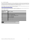
Notes:
1. All pins are in a single row, with a 1.27mm (0.050”) pitch.
2. The comments on the mating sequence apply to the case of backplane blindmate connector only. In this case, the mating sequences
are:
• the ground pins P4 and P12.
• the pre-charge power pins and the other ground pins.
• the signal pins and the rest of the power pins.
3. There are three power pins for each voltage. One pin from each voltage is used for pre-charge when installed in a blind-mate back-
plane configuration.
4. All used voltage pins (V
x
) must be terminated.
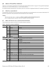
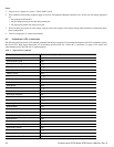
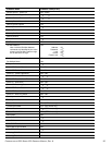
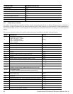
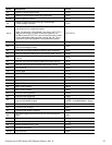
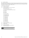
6.3 SUPPORTED ATA COMMANDS
The following table lists Serial ATA standard commands that the drive supports. For a detailed description of the ATA commands, refer to
the Serial ATA: High Speed Serialized AT Attachment specification. See “S.M.A.R.T. commands” on page 41.for details and
subcommands used in the S.M.A.R.T. implementation.
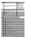
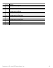
Table 9 Supported ATA commands
COMMAND NAME COMMAND CODE (IN HEX)
Check Power Mode E5
H
Download Microcode 92
H
Execute Device Diagnostics 90
H
Flush Cache E7
H
Flush Cache Extended EA
H
Identify Device EC
H
Idle E3
H
Idle Immediate E1
H
NoP 00
H
Read Buffer E4
H
Read Buffer DMA E9
H
Read DMA C8
H
Read DMA Extended 25
H
Read FPDMA Queued 60
H
Read Log DMA Ext 47
H
Read Log Ext 2F
H
Read Multiple C4
H
Read Multiple Extended 29
H
Read Native Max Address F8
H
Read Native Max Address Extended 27
H
Read Sectors 20
H
Read Sectors Extended 24
H
Read Sectors Without Retries 21
H
Read Verify Sectors 40
H
Read Verify Sectors Extended 42
H
Read Verify Sectors Without Retries 41
H
Request Sense Data Ext 0B
H