


Barracuda 180 Product Manual, Rev. A 21
6.0 Physical/electrical specifications
This section provides information relating to the drive’s physical and electrical characteristics.
6.1 AC power requirements
None.
6.2 DC power requirements
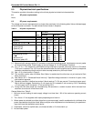
The voltage and current requirements for a single drive are shown in the following table. Values indicated apply
at the drive power connector. The table shows current values in Amperes.
Table 2: DC power requirements
[1] Measured with average reading DC ammeter or equivalent sampling scope. Instantaneous current peaks
will exceed these values. Power supply at nominal voltage. N = 6, 22 Degrees C ambient.
[2] For +12 V, a –10% tolerance is permissible during initial start of spindle, and must return to ±5% before
7,200 rpm is reached. The ±5% must be maintained after the drive signifies that its power-up sequence
has been completed and that the drive is able to accept selection by the host initiator.
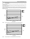
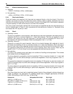
[3] See +12 V current profile in Figure 3.
[4] This condition occurs when the Motor Start Option is enabled and the drive has not yet received a Start
Motor command.
[5] See Section 6.2.1 “Conducted Noise Immunity.” Specified voltage tolerance is inclusive of ripple, noise,
and transient response.
[6] Operating condition is defined as random 8 block reads at 71 I/Os per second. Current and power speci-
fied at nominal voltages. Decreasing +5 volt supply by 5% increases 5 volt current by 2.9%. Decreasing
+12 volt supply by 5% increases +12 volt current by 2.4%.
[7] During idle, the drive heads are relocated every 60 seconds to a random location within the band from
track zero to one-fourth of maximum track.
General Notes from Table 2:
1. Minimum current loading for each supply voltage is not less than 1.8% of the maximum operating current
shown.
2. The +5 and +12 volt supplies shall employ separate ground returns.
3. Where power is provided to multiple drives from a common supply, careful consideration for individual drive
power requirements should be noted. Where multiple units are powered on simultaneously, the peak start-
ing current must be available to each device.
4. Parameters, other than spindle start, are measured after a 10-minute warm up.
5. No terminator power.
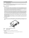
Notes
ST1181677
SE mode LVD mode
Voltage +5 V +12 V +5 V +12 V
Regulation [5] ±5% ±5%[2] ±5% ±5%[2]
Average idle current DCX
[1] 0.67 0.55 0.74 0.55
Maximum starting current
(peak DC) DC
(peak AC) AC
[3]
[3]
0.71
0.89
1.32
2.38
0.78
0.99
1.32
2.38
Delayed motor start (max) DC [1][4] 0.56 0.03 0.63 0.03
Peak operating current
DCX
Maximum DC
Maximum (peak) DC
[1][6]
[1]
0.70
0.71
1.25
0.81
0.91
2.25
0.81
0.83
1.52
0.81
0.91
2.25