


Barracuda 180 Product Manual, Rev. A 51
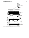
9.6.2 SCSI interface physical description
The drive models described by this product manual support the physical interface requirements of the Ultra160
SCSI Parallel Interface-3 (SPI-3) standards as defined in American National Standard document T10/1302D,
and operate compatibly at the interface with devices that support earlier SCSI-2 and SCSI-3 standards. It
should be noted that this is only true if the systems engineering has been correctly done, and if earlier SCSI-2
and SCSI-3 devices respond in an acceptable manner (per applicable SCSI Standards) to reject newer
Ultra160 protocol extensions that they don’t support.
The drives documented in this manual support single-ended and low voltage differential physical interconnects
(hereafter referred to as SE and LVD, respectively) as described in the ANSI SPI-3 standard. These drives
implement driver and receiver circuits that can operate either SE or LVD. However, they cannot switch dynami-
cally between SE and LVD operation.
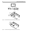
The drives typically operate on a daisy-chain interface in which other SCSI devices are also operating. Devices
on the daisy chain must all operate in the same mode, either SE or LVD, but not a mixture of these. On the
interface daisy chain, all signals are common between all devices on the chain, or bus, as it is also called. This
daisy chain of SCSI devices must be terminated at both ends with the proper impedance in order to operate
correctly. Do not terminate intermediate SCSI devices. In some cases, the SCSI devices at each end have
onboard termination circuits that can be enabled by installation of a jumper plug (
TE
) on the device. These ter-
mination circuits receive power from either a source internal to the device, or from a line in the interface cable
specifically powered for that purpose. LC/LCV and LW/LWV model drives do not have onboard termination cir-
cuits. Some type of external termination circuits must be provided for these drives by the end user or designers
of the equipment into which the drives will be integrated. See Standard T10/1302D, sections 6.6 and 6.7 for the
maximum number of devices that can successfully operate at various interface transfer rates on SE and LVD
daisy chains.
LC/LCV model drives plug into PCBA or bulkhead connectors in the host. They may be connected in a daisy-
chain by the host backplane wiring or PCBA circuit runs that have adequate DC current carrying capacity to
support the number of drives plugged into the PCBA or bulkhead connectors. A single 80-pin I/O connector
cable cannot support the DC current needs of several drives, so no daisy chain cables beyond the bulkhead
connectors should be used. A single drive connected via a cable to a host 80-pin I/O connector is not recom-
mended.
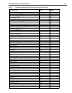
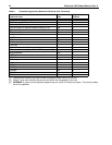
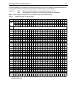
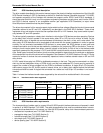
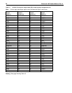
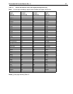
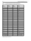
Table 11 shows the interface transfer rates supported by the various drive models defined in this manual.
Table 11: Interface transfer rates supported
9.6.3 SCSI interface cable requirements
The characteristics of cables used to connect Ultra160 SCSI parallel interface devices are discussed in detail
in section 6 of ANSI Standard T10/1302D. The cable characteristics that must be considered when intercon-
necting the drives described in this manual in a Ultra160 SCSI parallel, daisy-chain interconnected system are:
• characteristic impedance (see T10/1302D Section 6)
• propagation delay (see T10/1302D Section 6)
• cumulative length (see T10/1302D Section 6)
• stub length (see T10/1302D Section 6)
• device spacing (see T10/1302D Section 6)
Interface type/
drive models
Maximum transfer rate
Asynchronous Fast-5 Fast-10
Fast-20
(Ultra)
Fast-40
(Ultra2)
Fast-80
(Ultra160)
SE
Mode
ST1181677
LC/LCV
ST1181677
LW/LWV
yes yes yes yes no no
LVD
Mode
ST1181677
LC/LCV
ST1181677
LW/LWV
yes yes yes yes yes yes