


ST43401N/ND, ST43402ND User’s Manual, Rev. B 23
Installation procedures
With the site requirements completed, the enclosure designed, and the drive
unpacked you are ready to begin the installation. The following procedures are
included in drive installation:
• Setting the circuit board jumpers
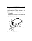
• Installing a power supply
• Attaching an optional bezel
• Mounting the drive
• Connecting the system I/O cabling
• Grounding the system
• Synchronizing the spindle
Setting the control board jumpers
Caution. Do not remove the circuit boards to set jumpers.
The circuit boards on the drive contain a number of jumpers that must be set
correctly for normal operation of the drive. The termination must also be set
correctly for normal operation.
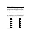
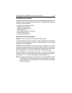
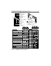
ST43401N and ST43401ND drives have two circuit boards—one control
board and one power board—but all of the necessary jumpers, including the
termination jumper and terminator resistor-pak sockets, are on the control
board. See Figure 8 to configure an ST43401N or ST43401ND drive.
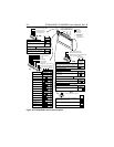
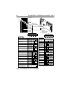
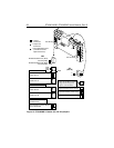
The ST43402ND drive has two circuit boards—one control board and one
I/O board—which must be configured correctly for normal drive operation.
See Figures 9, 10, 11, and 12 to configure an ST43402ND drive.
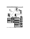
Note. The option pin headers on J10 (see Figure 11) are provided for manual
drive configuration. This helps you connect the disc drive to an external
device such as a switch or connection. Ground should be provided by
the external device.