


36 ST43401N/ND, ST43402ND User’s Manual, Rev. B
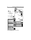
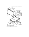
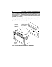
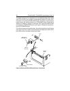
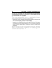
Figure 18 shows how the terminator resistor-paks are attached on ST43401ND
drives (differential I/O). These terminator resistor-paks, which are dual inline
packages, mount in sockets in the control board. These terminators are also
marked with a dot above pin 1.
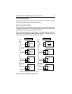
If the drive is located at either end of the daisy chain, ensure that it has
resistor-pak(s) installed. Refer to information earlier in this section re-
garding the terminator power source jumper.
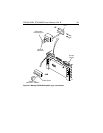
Terminator
Resistor-Pak
(note orientation)
Terminator
Socket
Terminator
Resistor-Paks
(part number
70906701)
Terminator
Power
Source Jumper
Pin 1
Figure 18. ST43401ND terminator attachment—differential I/O