


Section 1. Introduction
7
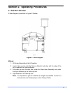
Hardware Overview (continued)
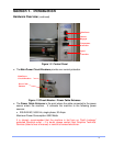
q Two Emergency Stop Buttons are fitted to the machine, located prominently on
top of both end cabinets. When pressed, all power is removed from the working
parts of the machine. The machine cannot be used again until the Emergency
Stop Buttons are reset twisting the button ¼ turn clockwise. When the
emergency stop buttons are reset, the laminator powers up and the power switch
must be reset to begin operation.
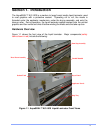
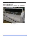
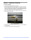
q The Draw Down Assembly is located directly over the Drip Tray and is used to
smooth the coating onto the surface of the media. It is manually raised and
lowered by pivoting the assembly into it’s up or down positions.
q The Dam Stop Assemblies are used to stop the coating from flowing off the
edges of the media during operation. They are positioned at the edges of the
media and are composed of two separate parts. An inner dam bracket is
positioned on top and at the edges of the media and outer bracket positions up
underneath the media to ensure that the dam stops hold a seal during operation.
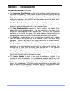
q The Drip Tray is located directly under the Draw Down Assembly and is used to
catch any drips of coating that may fall off the edge or end of the media during
operation. The Drip Tray pulls out the front of the machine for periodic cleaning.
The Sealant Recovery Trays sit inside the Drip Tray.
q The Sealant Tank is used to hold the supply of coating (18 liters/5 gallons). It is
positioned on an overhead stand located on the left cabinet of the machine. The
machine has no pump and the coating flows from the tank to the applicator
nozzle by gravity feed and is controlled with flow control valves.
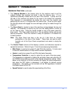
q The Applicator Nozzle is used to control the flow of coating delivered to the
surface of the media. Coating flows from the Sealant Tank to the Applicator
Nozzle and is flooded onto the surface of the media.
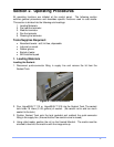
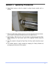
q The Unwind Mandrel is used to load a roll of media onto the front of the
machine for roll to roll operation. It is a cantilevered assembly located low on the
front of the machine. On the left side of the Unwind Mandrel is located a Tension
Braking mechanism for applying back tension to the web. It is adjusted by
turning the knurled collar. Core alignment is accomplished by sliding the core
onto the mandrel and positioning in the desired position. Once the drive starts
the Auto-grip bands will engage the core and enable the Tension Brake.