


33
Engli
s
h
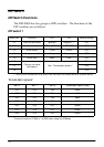
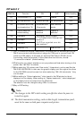
DIP switch 2
(*1)The “Y-connection enable” is set when a TM printer with no modular jack for the
DM-D is connected with this product, using one COM port to connect both TM
printer and DM display. In this case, an optional DM-D stand (DP-501) and a
connecting cable are required. In the cases other than above, choose
“Y-connection disable” (default setting).
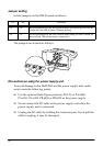
(*2)This function can select whether or not you perform self test when turning on the
power. See “Self Test” for details.
(*3)When selecting “20 column and 2 line mode,” this product can be used like the
DM-D105/106/205/206. In this case, the graphic display and the original functions
for the DM-D500 cannot be used, but when selecting “256 × 64 dots mode,” they
can be used.
(*4)When setting to “Printer is selected,” data is sent to the TM printer, but is not
displayed on the display. When setting to “Display is selected,” data is displayed
on the display but is not output from the TM printer.
The selection can be changed using <ESC=> command.
(*5)Stay at OFF setting.
Note:
❏
The changes in the DIP switch setting are effective when the power is
turned on again.
❏
The data transmission setting, such as data length, transmission speed,
must be the same on both your computer and printer.
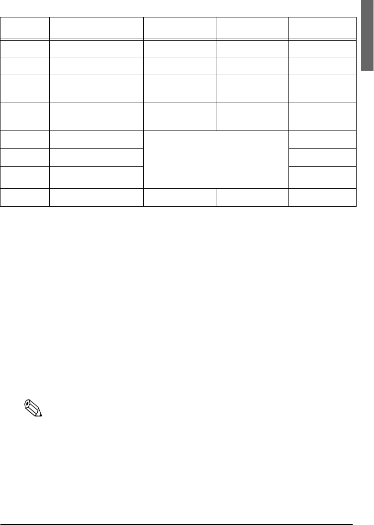
DSW2 No. Function ON OFF Default setting
2-1 Y-connection (*1) Enable Disable OFF
2-2 Self test selection (*2) Perform self test Do not perform OFF
2-3 20 column and 2 line
mode selection (*3)
20 column and
2 line mode
256 ¥ 64 dots
mode
OFF
2-4 Device selection
default setting
Printer is
selected
Display is
selected
OFF
2-5 Address 0 The display device number
(1-7) corresponds to Address num-
ber 0 to 2.
(All OFF are regarded as no dis-
play number.)
OFF
2-6 Address 1 OFF
2-7 Address 2 OFF
2-8 Reserved (*5) - Fixed to OFF OFF