


-11
5
10
15
1
11
6
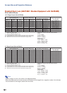
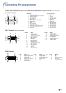
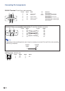
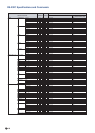
COMPUTER/COMPONENT input and COMPUTER/COMPONENT output Terminals: mini D-sub 15
pin female connector
Connecting Pin Assignments
RGB Input
1. Video input (red)
2. Video input (green/sync on green)
3. Video input (blue)
4. Not connected
5. Not connected
6. Earth (red)
7. Earth (green/sync on green)
8. Earth (blue)
9. Not connected
10. GND
11. Not connected
12. Bi-directional data
13. Horizontal sync signal: TTL level
14. Vertical sync signal: TTL level
15. Data clock
Component Input
1. P
R
(C
R
)
2. Y
3. P
B
(C
B
)
4. Not connected
5. Not connected
6. Earth (P
R
)
7. Earth (Y)
8. Earth (P
B
)
9. Not connected
10. Not connected
11. Not connected
12. Not connected
13. Not connected
14. Not connected
15. Not connected
1724
1
9
16
8
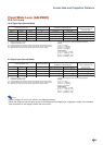
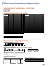
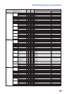
Pin No. Name
1T.M.D.S. Data 2–
2T.M.D.S. Data 2+
3T.M.D.S. Data 2 Shield
4 Not connected
5 Not connected
6 DDC Clock
7 DDC Data
8 Not connected
9T.M.D.S. Data 1–
10 T.M.D.S. Data 1+
11 T.M.D.S. Data 1 Shield
12 Not connected
13 Not connected
14 +5 V Power
15 Ground
16 Hot Plug Detect
DVI-D Terminal: 24 pin connector
Pin No. Name
17 T.M.D.S. Data 0–
18 T.M.D.S. Data 0+
19 T.M.D.S. Data 0 Shield
20 Not connected
21 Not connected
22 T.M.D.S. Clock Shield
23 T.M.D.S. Clock+
24 T.M.D.S. Clock–
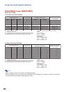
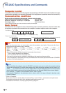
Pin No. Name
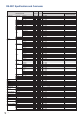
1T.M.D.S data 2+
2T.M.D.S data 2 shield
3T.M.D.S data 2–
4T.M.D.S data 1+
5T.M.D.S data 1 shield
6T.M.D.S data 1–
7T.M.D.S data 0+
HDMI Terminal
119
218
Pin No. Name
8T.M.D.S data 0 shield
9T.M.D.S data 0–
10 T.M.D.S clock+
11 T.M.D.S clock shield
12 T.M.D.S clock–
13 CEC
Pin No. Name
14 Reserved
15 SCL
16 SDA
17 DDC/CEC ground
18 +5V power
19 Hot plug detection