


-43
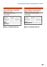
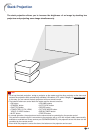
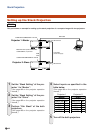
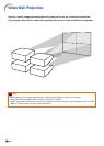
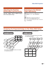
Stack Projection
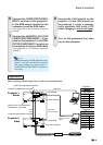
Projector 1:
Master
Projector 2:
Slave
Video equipment
Distributor
RGB cable
5BNC to
mini D-sub 15 pin
cable
Composite video cable
RGB
cable
MONITOR OUT (FOR COMPUTER/
COMPONENT1, 2)
terminal
COMPUTER/COMPONENT1
terminal
COMPUTER/COMPONENT1
terminal
COMPUTER/COMPONENT2
terminal
VIDEO
terminal
VIDEO
terminal
LAN
terminal
LAN
terminal
Computer
Computer
LAN cable
(cross-over type)
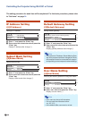
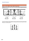
Master
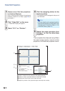
Set Inputs
ON
ON
OFF
OFF
ON
OFF
ON
OFF
OFF
OFF
ON
OFF
Slave
Set Inputs
COMPUTER1
COMPUTER2
DVI
HDMI
VIDEO
S-VIDEO
COMPUTER1
COMPUTER2
DVI
HDMI
VIDEO
S-VIDEO
Projector 1
Projector 2
6 Connect the COMPUTER/COMPO-
NENT1 terminal on the projector 1
to the RGB output terminal on the
computer using the RGB cable.
(See page 24 on the projector operation
manual.)
7
Connect the MONITOR OUT (FOR
COMPUTER/COMPONENT1, 2) ter-
minal on the projector 1 to the COM-
PUTER/COMPONENT1 terminal on
the projector 2 using an RGB cable.
(See page 27 on the projector operation
manual.)
Note
• When connecting an RGB cable to the pro-
jector 2, use the input terminal that has
the same number as the projector 1.
(COMPUTER/COMPONENT1 terminal, in
this case)
8 Connect the LAN terminal on the
projector 1 to the LAN terminal on
the projector 2 using a commer-
cially available LAN cable (UTP
cable, Category 5,
cross-over type).
9 Turn on the projectors first, then
turn on the computer.
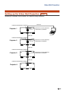
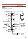
Application
When inputting multiple image sources, refer to the example below.