


ENGLISH
ENGLISH
– 4 –
1
234
6
7
8
9
10
11
12
5
1
2
3
4
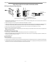
FIGURE 4
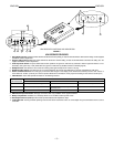
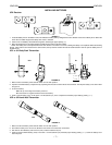
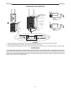
UC1 TRANSMITTER FEATURES AND CONTROLS
1. Antenna. A flexible 1/4 wave whip antenna is permanently
attached to the top of the UC1 Body-Pack transmitter.
2. Power/Battery Fuel Gauge. When the Power switch is in
the ON position, one of the three LEDs will glow, indicating
that the transmitter is on. The LED color indicates the
amount of battery life remaining. Refer to the Checking Bat-
teries section.
3. ON/OFF Switch. Turns transmitter power on and off.
4. Input Connector (LEMO connector optional). This Mini
connector (TA4F ) provides connection with a variety of lavali-
er, instrument and headset microphones and cables. LEMO
connectors are available as an option.
5. Remote Mute Switch Input Connector. When used with
the optional Shure UA101 Remote Mute Switch, this 3.5 mm
connector lets you remotely mute the body pack during a
performance.
6. Group Setting Control (Red Switch). Rotating this switch
clockwise advances the Group setting. Rotating it counter-
clockwise decreases the Group setting. Use the supplied
screwdriver to make adjustments.
7. Channel Setting Control (Green Switch). Rotating this
switch clockwise advances the Channel setting. Rotating it
counterclockwise decreases the Channel setting. Use the
supplied screwdriver to make adjustments.
8. Input Attenuation Control. This two position switch lets
you select either 0 dB or –20 dB attenuation, depending on
the input source and application. For most microphone ap-
plications, the 0 dB setting is appropriate.
9. Audio Gain Control. This control changes the audio level
to accommodate different sound sources. The factory set-
ting is at mid level, which is appropriate for most microphone
applications, except headphone microphones (Refer to the
“Adjusting the Transmitter Gain Level” section). Use the
supplied screwdriver to make adjustments.
10. Battery Compartment. One 9V battery is required.
11. Battery Compartment Cover. Hinged cover on front sur-
face opens to expose the battery and Group/Channel, Gain,
and Attenuation controls.
12. Battery Cover Release Tabs. Squeeze these two tabs to-
gether to release the battery cover.
13. Belt Clip (not shown). Allows the transmitter to be worn on a
belt, waistband, or guitar strap. The belt clip can be rotated 180°.
1
5
3
7
4
8
6
2
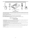
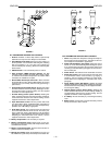
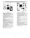
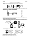
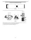
FIGURE 5
UC2 TRANSMITTER FEATURES AND CONTROLS
1. Grille. This protects the microphone cartridge and helps re-
duce breath sounds and wind noise. The grilles for the vari-
ous microphone heads differ in appearance.
2. Power Indicator/Battery Fuel Gauge. When the UC2 is
turned on, one of three LEDs will glow, indicating that power
is on and the amount of battery life remaining. Refer to the
“Checking Transmitter Battery” paragraph for more informa-
tion on battery life.
3. Power Switch. This switch turns the transmitter on and off.
4. Audio Gain Control. This control changes the audio level
to accommodate various sound sources (e.g. singing or
speaking). Use the supplied screwdriver to make adjust-
ments. Refer to the “Adjusting the Transmitter Gain Level”
paragraph.
5. Group Setting Control (Red Switch). Rotating this switch
clockwise advances the Group setting. Rotating it counterclock-
wise decreases the Group setting. Use the supplied screwdriv-
er to change the setting.
6. Channel Setting Control (Green Switch). Rotating this
switch clockwise advances the Channel setting. Rotating it
counterclockwise decreases the Channel setting. Use the
supplied screwdriver to make adjustments.
7. 9 V Battery. Access the battery by unscrewing the battery
cover.
8. Battery Cover. Unscrew this to expose the battery and the
Group, Channel and Gain controls.