


ENGLISH
ENGLISH
– 5 –
ON OFF
1
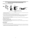
FIGURE 6
10
11
12
13
2
3
4
5
1
9
8
7
6
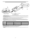
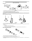
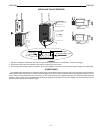
U1 TRANSMITTER CONTROLS & INDICATORS
1. Antenna. A 1/4 wave antenna is permanently attached to
the top of the U1 body-pack transmitter. The antenna can be
replaced in the field by a qualified technician.
2. Programmable Display. This display provides information
on group and channel settings, battery power level, and fre-
quency lock/power lock on/off status.
3. Input Connector. This connector functions with a variety of
lavalier and headset microphone cables, and the Shure
WA302 instrument adapter cable. LEMO–type connectors
are available as an option.
4. ON/OFF Switch. This switch turns transmitter power on
and off.
5. On/Off LED. When the U1 is turned on, this glows green.
6. Belt Clip. This allows the transmitter to be easily worn on
a belt, waistband or guitar strap.
7. MODE Button. This button allows you to chose between
changing the Group or the Channel setting.
8. SET Button. This button changes transmitter Group and
Channel settings. Also used with the MODE button to lock
power on and to lock the frequency and channel setting.
9. Audio Gain Control. This allows audio level adjustment to
accommodate a variety of sound sources (speaking, sing-
ing, or playing an instrument). A small screwdriver is sup-
plied for making adjustments.
10. Battery Cover Release Tabs. Squeeze these two tabs to-
gether to release the battery cover.
11. Battery Compartment Cover. Hinged cover on front sur-
face opens to expose the battery and display control keys.
12. Battery Fuel Gauge. This meter visually indicates battery
power level.
13. Battery Compartment. Two 1.5V AA batteries are re-
quired. (Duracell
R
MN1500 recommended).
ON
OFF
GAIN
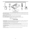
FIGURE 7
1
2
4
5
6
3
7
8
9
10
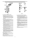
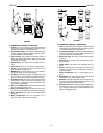
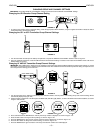
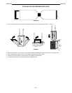
U2 TRANSMITTER CONTROLS & INDICATORS
1. Grille. The grille protects the microphone cartridge and helps
reduce breath sounds and wind noise. The grilles for the vari-
ous microphone heads differ in appearance.
2. Programmable Display. This display provides information
on the Group and Channel settings, battery power level, and
frequency lock/power lock on/off status.
3. Battery Fuel Gage. This meter visually indicates battery
power level.
4. Battery Cover. Unscrew this to expose batteries and dis-
play control keys.
5. ON/OFF Switch. This switch turns transmitter power on
and off.
6. Antenna. Helical antenna is attached to the end of the U2
transmitter. The antenna can be replaced in the field by a
qualified technician.
7. Battery Compartment. Two 1.5 V AA batteries are re-
quired.
8. MODE Button. This button allows you to chose between
changing the Group or the Channel setting.
9. SET Button. Changes transmitter Group and Channel set-
tings. Also used with the MODE button to lock power on and
to lock the frequency and channel setting.
10. Audio Gain Control. This allows audio level adjustment to
accommodate a variety of sound sources (speaking, sing-
ing, or playing an instrument). A small screwdriver is sup-
plied for making adjustments.