


Hardware and Software Installation
Note: The MP modem is
designed for negative-ground
vehicles only. It will not function
in a positive-ground vehicle.
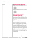
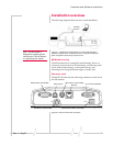
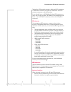
Figure 2-2: MP 875 modem rear connectors
I/O connector (DB15HD)
RS-232 serial (female DB9)
USB (Type B)
GPS antenna (female SMA)
Ethernet
Power harness (Molex connector)
RF antenna (female TNC)
Serial Host
USB Host
GPS
Ethernet Host
I/O
RF
Power
21
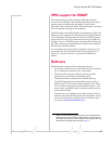
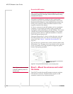
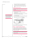
Installation overview
The following diagram illustrates the overall installation.
Figure 2-1: Installation of the MP modem in a vehicle equipped with a
notebook computer and a combination antenna, using the car battery for
power and ignition-sense wiring for power on/off.
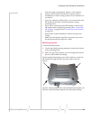
MP Modem housing
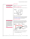
The MP modem has a rectangular metal housing. There is a
connector panel on the rear of the housing, an indicator panel
on the front of the housing, a reset button on top, and
mounting holes along the bottom edges on either side.
Connector panel
The MP 875 modem has the following connectors at the rear of
the MP modem:
RF/GPS
antenna
MP modem
Rev 1.1 Aug.07