


MP 875 Modem User Guide
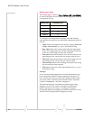
Note: No more than 36 VDC
should be applied to any I/O
pins.
Before using the digital input/output lines, you must configure
them as inputs or outputs.
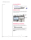
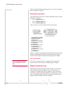
Connector pinouts
The MP modem’s I/O port is a female DB15HD connector with
eight active I/O pins:
• Two (2) digital I/O pins.
• Two (2) digital input pins.
• Four (4) analog input pins.
There are also six reserved pins and one ground pin.
1
5
6
10
11
15
DB15HD male cable
DB15HD female connector
on rear of MP modem
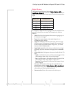
1.
Reserved—do not connect
2.
Reserved—do not connect
3. Digital Input/Output 1
4. Digital input 3
5.
Reserved—do not connect
6.
Reserved—do not connect
7. Analog input 2
8. Analog input 4
9.
Reserved—do not connect
10. Ground (GND)
11. Digital Input/Output 2
12. Digital input 4
13.
Reserved—do not connect
14. Analog input 1
15. Analog input 3
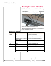
Figure 4-1: Pinouts for a male DB15HD I/O cable (left) that connects to the MP
modem’s female DB15HD I/O connector (right). Note that the two figures’
pinouts are mirror images of each other, since they plug into one another.
Port specifications
See “I/O port characteristics” on page 62 for the technical
specifications of the I/O ports, including input voltages.
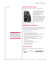
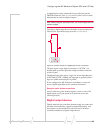
Digital input devices
Digital input devices are those that have only two states and
send a signal to the MP modem in one of those states. An
example of a digital input device might be a gun rack alarm
that sends a signal to the MP modem any time the gun rack is
open. Another example would be a panic button that sends a
signal to the MP modem when it is pushed.
44 2130808