


MP 875 Modem User Guide
Note: 5-m part number:
6000083.
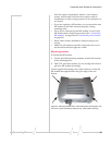
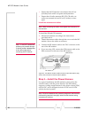
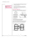
You can connect the MP modem Ethernet port directly to a
computer or other Ethernet device with either a cross-over
or a straight-through cable.
• A serial cable (with a DB9 connector on the MP modem
end). The maximum length of the serial cable is 5.5-m
(18 feet). Sierra Wireless sells suitable serial cables in 5-m
(16-feet) lengths.
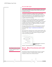
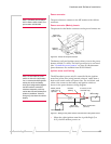
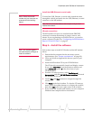
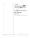
Serial connector (DB9) pinouts
The MP modem is configured as DCE (Data Communications
Equipment) and uses the standard RS232 pin designations:
DB9 MALE
1
5
DB9 female connector
6
9
1. Data Carrier Detect (DCD)
2. Transmitted Data (TxD)*
3. Received Data (RxD)*
4. Data Terminal Ready (DTR)
5. Signal Ground (GND)
6. Data Set Ready (DSR)
7. Clear To Send (CTS)
8. Request To Send (RTS)
Serial Host
RF
USB Host
9. Ring Indicator (RI)
* RxD and TxD are named with respect to the MP modem
(that is, RxD is the Receive Data input to the MP modem,
and TxD is the transmit data out of the MP modem.)
Figure 2-8: Pinouts for an RS232 male DB9 serial cable (left) that connects to
the MP 875 modem’s female DB9 serial connector (right). Note that the two
figures’ pinouts are mirror images of each other, since they plug together.
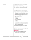
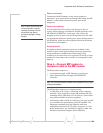
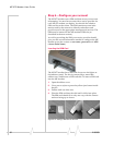
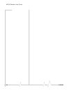
The serial connector uses these voltage specifications:
RS-232-C
RS-232-C
Driver
Receiver
+15 V
+15 V
2 V
noise margin
+5 V
⎬
+3 V
-3 V
-5 V
Mark logic 1 Mark logic 1
-15 V
-15 V
Figure 2-9: Voltage specifications for the MP modem’s serial connector.
Space logic 0
Transmission
region
Space logic 0
Transmission
region
30 2130808