


Configuring the MP Modem to Report GPS and I/O Data
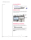
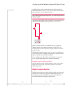
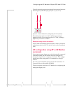
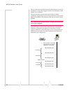
Typically an analog input device should be connected between
Ground (pin 10) and the input port (Pin 7, 8, 14, or 15).
~
Figure 4-4: A sensor wired to Pin 7 (analog input) and Pin 10 (Ground).
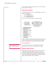
The analog input ports use a 10-bit (1024-step) analog-to-
digital converter over a range from 0 to 3.45 VDC, yielding a
digital step resolution of 0.0032 V.
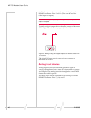
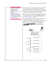
Example: analog sensor connections
An I/O cable for an analog sensor requires a wire to one of the
analog input pins (such as #7) and one wire to the Ground pin
(#10).
I/O configuration using AT or 3G Watcher
commands
Once a sensor, gauge, button, or switch is physically connected
to the MP modem, the MP modem must be configured to
manage the input from, or output to, the device. This configu-
ration can be done using either AT commands or using 3G
Watcher.
For a list of AT commands, please see the MP 3G Modems AT
Command Reference (document #2130810).
There are separate windows in 3G Watcher for configuring the
analog and digital ports.
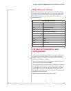
Rev 1.1 Aug.07 47