14811 • January 2005 • Operation
Page 9
Configurable Parameters/Menu Items
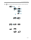
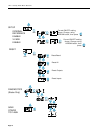
Note: What follows is a discussion of the configurable parameters in the DA5320. To
view a diagram of the flow of the menu structure with simple operating instructions,
see the section of the manual entitled MENU STRUCTURE that follows this
discussion.
There are a number of items that are configurable on the DA5320. These fall into two basic
categories - Input Parameters and Output Parameters. Additionally, there are some diag-
nostic, reset and memory storage functions that can be accessed from the front panel
through the menu commands.
Input Parameters
Each DA5320 is an 8X8 AES Digital Audio router that can route the signals that are physi-
cally connected to it or any of the other 56 channels available on the OctaBus™. Which of
the available signals it should consider to be Inputs is defined under the menu item.
With this menu item the operator defines, by selecting the OctaBus™ ID and the channel
number, exactly which signal on the OctaBus™ should be defined as each of the num-
bered inputs (1-8) to the module being configured, without regard to the physically con-
nected inputs to the module.
NOTE: If OctaBus™ is not enabled, requests for inputs defined as being from other
modules (OctaBus™ ID’s other than 1), will generate an ERROR condition.
Each of the defined inputs may also have a gain value assigned to them to adjust their
incoming level to the mixer or router stages. This gain adjust is adjusted via the
menu item that appears under the main menu selection by specifying the gain factor
for each channel. The gain can be adjusted in 1 dB increments.
Output Parameters
Due to the nature of some of the parameters able to be modified, for example enabling out-
puts, it may be desired to change all or selected groups of outputs simultaneously. To
accommodate this, grouping of outputs is provided. Output grouping does not apply to rout-
ing functions in the DA5320 . Output grouping is the first parameter detailed in this section.
If the module being configured is to be a part of a system that utilizes the OctaBus™, this
feature must be activated. This feature is detailed in the OctaBus™ ID Assignment section
below.
To operate as a 64 X 8 channel router, the definiton of which of the defined inputs should
be routed to specific outputs must be detailed. As a mixer, which inputs will be mixed as
they are directed to the outputs must also be defined. Finally, the level of the signal to be


