14811 • January 2005 • System Components
Page 3
SYSTEM COMPONENTS
Frame
The DA5320 module is engineered to operate in a Sigma S5000 Signal Management
Frame. This frame provides all the necessary interface components and power for opera-
tion of the DA5320 module.
Interface Components
To accommodate a variety of connector requirements necessary for the signal formats
accepted by the S5000 Signal Management System, a number of backplanes are avail-
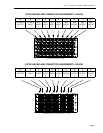
able. The DA5320 requires either an RP302 Twisted Pair I/O or RP303 BNC I/O Back-
plane.
Each S5000 Signal Management System frame is supplied with two (2) backplanes. The
required backplane(s) is specified at the time of order. If an existing frame does not have
the required backplane, replacement backplanes are available from Sigma Electronics and
can easily be installed in the field.
Power
The S5000 Signal Management System frame provides the required power to operate the
DA5320 via the backplane adapter. Dual power supplies are available for redundant appli-
cations.
Modules
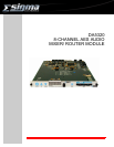
The DA5320 consists of a single-slot card containing a front panel interface of switches,
indicator LED’s and a four-digit, seven-segment LED display. Via this interface all common
configuration settings and status indications are available to the user.
Optionally, if a CI5705 Communications Interface Adapter is installed in the S5000 Signal
Management System frame, the DA5320 may be configured and controlled from a remote
location via the EIA-485 port. The CI5705 is also necessary if an external video reference
is required.


