


14811 • January 2005 • Operation
Page 12
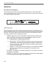
any valid NTSC or PAL video signal or AES Digital Audio. The DA5320 will match its ouptut
signal timing to be synchronized to this reference.
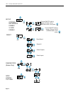
To have the DA5320 match its output signal timing to the internal reference the
menu setting must be set to ON.
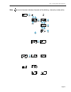
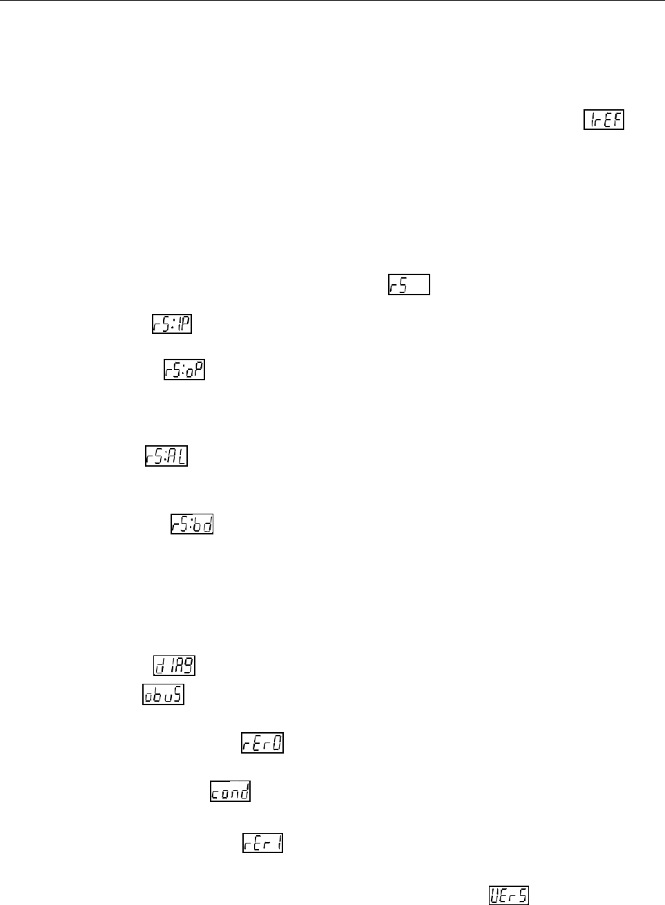
Reset Type/Initiation
Occasionally it may be necessary, or convenient, to clear the data stored in memory by
resetting the DA5320. Because it may be desirable to erase only some of the data, there
are six different Reset levels available in the DA5320. They are labeled Input, Output, ALL
and Board. All reset options are accessed under the menu item.
a. Input - - resets the source of all inputs. Inputs will be set to the physical
inputs of the module, 1=1, 2=2, 3=3, etc.
b. Output - - This type of reset clears all values stored defining the source
of the signal connected to each output. All values will be set correlating the
actual inputs of the module to its equivalent output, In 1 to Out 1, In 2 to Out
2, In 3 to Out 3, etc.
c. ALL - - This type of reset clears all stored values defining every
parameter. on the module. This is a combination of all the previously defined
Reset functions.
d. BOARD - - This type of reset includes all the capabilities of the ALL
reset but also toggles power to the board initiating the Power-On Self Test.
Diagnostic Data Display
If, at any time, the DA5320 encounters any anomalies with the data on the OctaBus, the
red, ERROR LED will be illuminated in the front panel and an error message will be stored
for display when the menu item is accessed. The OctaBus error categories to be
reported under the menu item are
A. OctaBus receive error 0
B. OctaBus state error
C. OctaBus receive error 1
To assist the technicians in the unlikely event of a service call, the menu item will
display the version number of the software used to program the DA5320.