14811 • January 2005 • Operation
Page 11
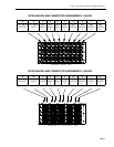
Output Channel Assignment/Mixing/Gain Control
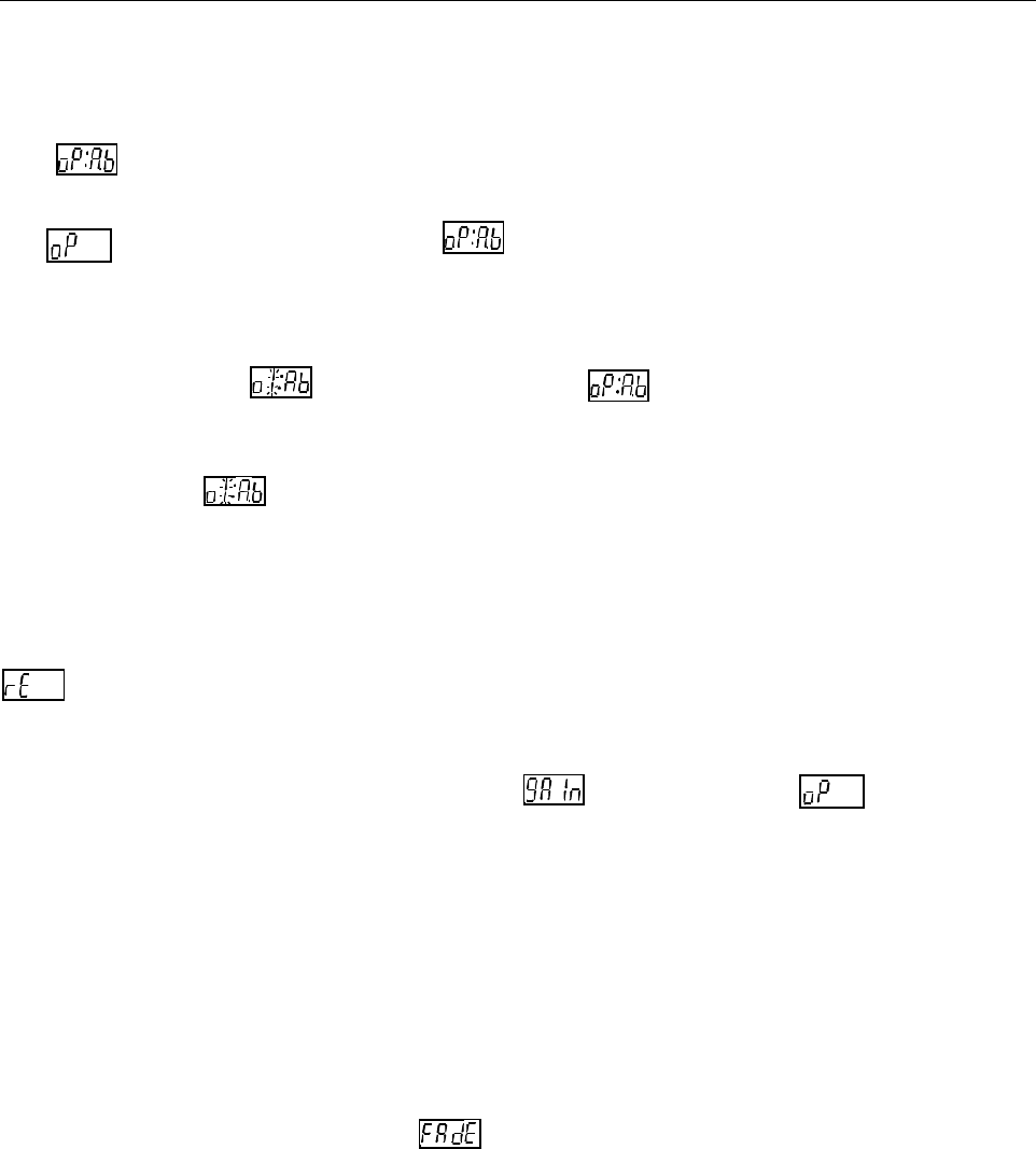
The sub-menu item is used to configure the routing matrix of defined inputs to spe-
cific physical output connectors and the mixing operation of the DA5320. It is located under
the main menu item. When the menu item is initially selected, it displays the
current mix selection for the selected output.
This menu item also allows selection of which channels are to be mixed to create the spec-
ified ouput. When the screen that follows the menu item has data entered into
it, the actual channels to be mixed will be defined. If the data entered is 1:5.6, then Output
1 will consist of equal parts of input channels 5 and 6 (50% gain on each channel). If the
data entered into were 1:5.-, then Output 1 would consist of only input channel 5 (“-”
is the selection for redundant input) with unity gain on channel 5.
The DA5320 is capable of much greater flexibility in its mixing operations when controlled
via the serial port on the rear of the S5000 frame. If a mix has been defined in this manner
that is not able to be displayed through the front panel selection, the display will show
indicating that the setting was made via the remote feature.
Each mixed signal may have a gain value applied to adjust the signal level sent to the
ouput connector. The gain is adjusted via the menu item under main menu
selection by specifying the gain factor for each output channel. The gain can be adjusted in
1 dB increments.
V-fades
The V-fade parameter enables the DA5320 to conceal AES framing errors that occur
upstream due to asynchronous switching or signal interruptions. With V-fade enabled, fast
error transitions (clicks and pops) are eliminated.
V-fades can be enabled through the menu item in Set-up.
Output Synchronization
The internal reference signal used for output synchronization is introduced into the frame
through a connector on the rear panel of the S5000 Signal Management System frame
labeled Video Reference. This reference is distributed throughout the frame by the CI5705
Communications Interface located above the power supplies. The reference signal can be


