


ELECTRICAL SPECIFICATION SSD-CXXX(I)-3600 DATA SHEET
SILICONSYSTEMS PROPRIETARY
This document and the information contained within it is confidential and proprietary to SiliconSystems, Inc.
All unauthorized use and/or reproduction is prohibited.
3600C-04DSR PAGE 10 FEBRUARY 2, 2009
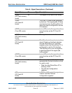
-IORD
(PC Card memory
mode)
34 I This signal is not used in this mode.
-IORD
(PC Card I/O
mode)
This is an I/O read strobe generated
by the host. This signal gates I/O data
onto the bus from the SiliconDrive CF
when the card is configured to use the
I/O interface.
-IORD
(True IDE mode)
In true IDE mode, this signal has the
same function as the PC Card I/O
mode.
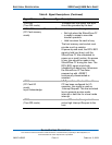
-IOWR
(PC Card memory
mode)
35 I This signal is not used in this mode.
-IOWR
(PC Card I/O
mode)
The I/O write strobe pulse is used to
clock I/O data on the Card data bus
into the SiliconDrive CF controller
registers when the SiliconDrive CF is
configured to use the I/O interface.
The clocking occurs on the negative-
to-positive edge of the signal (the
trailing edge).
-IOWR
(True IDE mode)
In true IDE mode, this signal has the
same function as the PC Card I/O
mode.
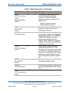
-OE
(PC Card memory
mode)
9 I This is an output enable strobe
generated by the host interface, which
is used to read:
• Data from the SiliconDrive CF in
memory mode.
• The CIS and configuration
registers.
-OE
(PC Card I/O
mode)
In PC Card I/O mode, this signal is
used to read the CIS and
configuration registers.
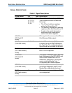
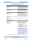
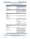
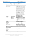
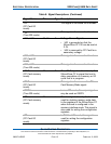
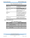
Table 8: Signal Descriptions (Continued)
Signal Name Pin Type Description