


14
ht3000e
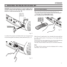
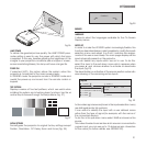
of the pictures reproduced by the HT3000E in the two cases:
the deinterlacing performed by the HT3000E is often more
effective than that performed by the source itself.
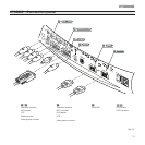
GRAPHICS RGB / YPrPb
This input should be connected to an RGB-type or YPrPb-type
video signal using a cable with a DB15HD type connector.
Using RGB-type signal, your source device must be able to
provide separate H/V synchronisation, composite H+V synchro-
nisation or composite synchronisation on green (RGsB).
Using YPrPb-type signal, your have to provide Pr signal at red
pin, Y at green and Pb at blue.
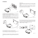
HDMI™
HDMI™ (High Definition Multimedia Interface) integrates an
uncompressed high definition video signal with a multichannel
audio signal and allows exchange of control data between the
video source and the HT3000E.
The HDMI input allows connection to video sources that use the
HDCP (High-Bandwidth Digital Content Protection) protocol to
protect their contents.
Once the video source has been connected to the HDMI
input, internal processing by the HT3000E separates the video
information from the audio information. The audio information
is made available on a digital output with a female TOSLINK
connector in compliance with the S/PDIF standard.
You can use a DVI-D > HDMI adapter cable to connect the
DVI-D signal from a source equipped with a DVI-D output.
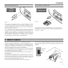
COMPOSITE VIDEO
Fit an RCA connector with a Composite Video (CVBS) signal
to this input.
The output connector on the external appliance is normally
coloured yellow and will often be labelled VIDEO.
Other signal and socket formats may be preferable (because
they give better image quality), but this type of output socket is
still the most commonly used, and nearly all television receivers,
video recorders, DVD players and camcorders, etc. use it.
S-VIDEO
Fit a mini-DIN connector with an S-Video signal to this input.
The corresponding output at the external device is normally
identifiable by the labels S-VIDEO or Y/C.
This type is nearly as common as Composite Video, and is
preferable to the latter, since it gives higher image quality.
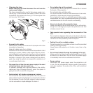
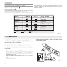
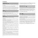
RGB/YPrPb
These inputs use a set of 4 RCA connectors.
RGB and Component signals can be applied to each set of
connectors.
RGB signals can have composite synchronisation on the green
signal (RGsB), or on the HV signal.
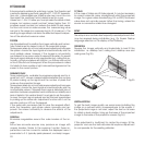
Connect the R, G, B outputs of the source to the respective R, G,
B inputs of the HT3000E (taking care not to invert the positions)
and any synchronisation signals to the HV.
When hooking up, use the colours of the RCA connectors as
an aid as follows: the R connector is red, G is green, B is blue
and HV is white.
You can use a SCART to RCA adapter cable to connect the
RGB signal from a source equipped with a SCART output to
this input.
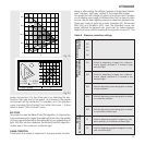
The Component signals connect to the Y, Pr and Pb inputs:
take care that the inputs correspond to the outputs on the
source device.
Since these can be labelled differently, refer to Table 1 to
establish the correspondence between the various signals. As
indicated in the table, the colours of the connectors can also
be of help.
Only horizontal scanning frequencies of 15 kHz (standard video
resolution) or 32 kHz (high definition video, with progressive
scanning) can be applied to this input.
Progressive signals usually provide better quality than interlaced
signals, but if the source features both progressive and deinter-
laced signal outputs it is good practice to compare the quality
1
2
3
4
5
6