


Functional Description Zeus SSD Functional Blocks
14 Zeus Ultra DMA Solid State Drives
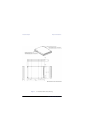
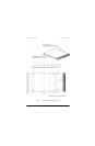
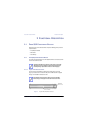
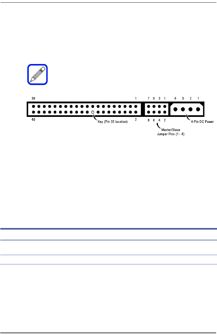
2.1.1.2 3.5-inch SSD ATA Interface and Power Connectors
The 3.5-inch Zeus-series SSDs are equipped with a 40-pin, DC power/ATA bus
combination connector (Figure4), located at the rear of the drive. IDE bus traffic is
supplied through a non-shielded 40-conductor I/O cable. DC power is supplied through
a separate 4-conductor power cable.
Figure 4. 40-pin ATA (IDE) Bus/DC Power Combination Connector
2.1.1.3 IDE Interface Connector Pinout Configuration
Table4 provides the signal assignment for each pin (electronic contact) on the ATA (IDE)
bus connectors used on Zeus SSDs. Except as noted, the table applies to both the 44-
pin ATA bus connectors (Figure3 on page13) on used 2.5-inch drives, and the 40-pin
ATA bus/DCpower combination connectors (Figure 4 above) used on 3.5-inch drives.
ATA standards require 80-conductor cables to be used for UltraDMA
modes 3 through 5. The length of the cable shall not exceed 18 inches.
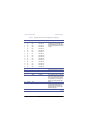
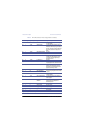
Table 4. ATA (IDE) Connector Pinout Configuration
Pin Pin Type Signal Symbol Signal Name Signal Description
1 I -RESET HOST RESET Reset signal from the host. Reset is active
on power up and inactive thereafter.
2 Ground GND — Ground
Continued