


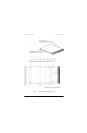
Zeus SSD Functional Blocks Functional Description
Zeus Ultra DMA Solid State Drives 15
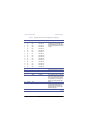
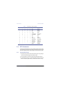
3 I/O D07 HOST DATA 7 Pins 3 through 18 (16 lines (15-0)) carry the
data between the controller and the host.
The low 8 lines transfer commands and the
ECC information between the host and the
controller.
4 I/O D08 HOST DATA 8
5 I/O D06 HOST DATA 6
6 I/O D09 HOST DATA 9
7 I/O D05 HOST DATA 5
8 I/O D10 HOST DATA 10
9 I/O D04 HOST DATA 4
10 I/O D11 HOST DATA 11
11 I/O D03 HOST DATA 03
12 I/O D12 HOST DATA 12
13 I/O D02 HOST DATA 02
14 I/O D13 HOST DATA 13
15 I/O D01 HOST DATA 01
16 I/O D14 HOST DATA 14
17 I/O D00 HOST DATA 0
18 I/O D15 HOST DATA 15
19 Ground GND — Ground
20 — — — No connection. Reserved for connector key.
21 O DREQ DMA REQUEST Not used
22 Ground GND — Ground
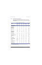
23 I -IOWR I/O WRITE This I/O Write strobe pulse is used to clock
I/O data or commands on the drive data bus
into the Drive controller registers when the
drive is configured to use the I/O interface.
The clocking will occur on the negative to
positive edge of the signal (trailing edge).
24 Ground GND — Ground
25 I -IORD I/O READ This is a Read strobe generated by the host.
The signal gates I/O data or status on the
host bus and strobes the data from the
controller into the host on the low to high
transition (trailing edge).
26 Ground GND — Ground
Continued
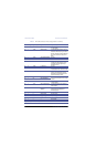
Table 4. ATA (IDE) Connector Pinout Configuration (Continued)
Pin Pin Type Signal Symbol Signal Name Signal Description