


Functional Description Zeus SSD Functional Blocks
16 Zeus Ultra DMA Solid State Drives
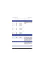
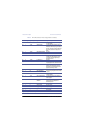
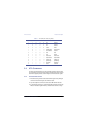
27 I IORDY I/O READY Not used, and pulled up to Vcc through a
4.7k ohm resistor.
28 I -CSEL CABLE SELECT This internally pulled up signal is used to
configure the drives as the Master or the
Slave device. When the pin is grounded, the
device is configured as a Master. When the
pin is open, the device is configured as a
Slave.
29 I -DACK DMA ACKNOWLEDGE Not used
30 Ground GND — Ground
31 O INTRQ INTERRUPT REQUEST This is an interrupt request from the
controller to the host, asking for service.
This signal is the active high Interrupt
Request to the host.
32 O -IOS16 I/O SELECT 16 Not used
33 I A1 HOST ADDRESS 1 This address line (A1) is used to select one
of eight registers in the controller Task File.
34 I/O -PDIAG After an Executive diagnostic command to
indicate to the Master it has passed its
diagnostics, this bi-directional open drain
signal is asserted by the Slave.
35 I A0 HOST ADDRESS 0 These address lines (A0 and A2) are used to
select one of eight registers in the controller
Task File.
36 I A2 HOST ADDRESS 2
37 I -CS1 HOST CHIP SELECT 1 The chip select signal used to select the
Task File register.
38 I -CS2 HOST CHIP SELECT 2 The chip select signal used to select the
Alternate Status register and the Device
Control register.
39 I/O -DASP DISK ACTIVE/SLAVE
PRESENT
This input/output is the Disk Active/Slave
Present signal in the Master/Slave
handshake protocol.
40 Ground GND — Ground
41* — V
CC
Supply Voltage 5V power supply
42* — V
CC
Supply Voltage 5V power supply
43* Ground GND — Ground
44* — — — No connection
* Applies to 44-pin, 2.5-inch SSD only
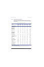
Table 4. ATA (IDE) Connector Pinout Configuration (Continued)
Pin Pin Type Signal Symbol Signal Name Signal Description