


SONY CAV-CVS12ES (US) 3-198-136-11(1)
7
US
Getting Started
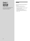
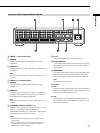
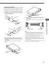
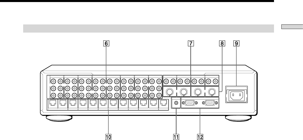
Rear panel of the Component Video Switcher
~
ACIN
SOURCE12
OUTIN
S12
ASSIGNABLE
SOURCE11
OUTIN
S11
ASSIGNABLE
SOURCE10
OUTIN
S10
ASSIGNABLE
SOURCE9
OUTIN
S9
ASSIGNABLE
SOURCE8
OUTIN
SOURCE7
OUTIN
SOURCE6
OUTIN
SOURCE5
OUTIN
SOURCE2
OUTIN
SOURCE1
OUTIN
Y
PB
PR
SOURCE4
OUTIN
SOURCE3
OUTIN
ZONE3
VIDEOOUT
ZONE2
VIDEOOUT
ZONE1
VIDEOOUT
ZONE4
VIDEOOUT
ZONE5
VIDEOOUT
ZONE6
VIDEOOUT
ZONE7
VIDEOOUT
ZONE8
VIDEOOUT
ZONE9
VIDEOOUT
ZONE10
VIDEOOUT
ZONE11
VIDEOOUT
ZONE12
VIDEOOUT
IRREMOTE
IN
RS-232C
CAVAUX
SOURCE 1 ~ 8 connection jacks
a) VIDEO IN
An RCA jack for component video input from a source
component.
b) VIDEO OUT
An RCA jack for connecting a video source to another local
component.
Note
The video loop-through output is not active when the Main Unit is
turned off.
SOURCE 9 ~ 12 connection jacks
a) VIDEO IN
An RCA jack for composite video input from a source
component.
b) VIDEO OUT
An RCA jack for connecting a video source to another local
component. The composite video signal is up-converted to
the component video signal automatically.
Note
The video loop-through output is not active when the Main Unit is
turned off.
ASSIGNABLE switch for SOURCE 9 ~ 12
Assign the source component connected to source 9 ~ 12 to
source 1 ~ 8. For example, when the SOURCE 9
ASSIGNABLE switch is set to “1”, the source 9 video signal is
distributed to the zone selected for source 1.
Notes
Set the ASSIGNABLE switch to “0” when you do not use the
assign function.
When you assign two or more source components to the same
source number, the assigned source numbers of SOURCE
indicator blink as an error indication.
AC IN
Connects the supplied AC power cord to AC IN.
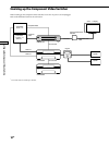
ZONE VIDEO OUT
A CAT5 RJ45 connector that sends a source video signal to
the component video input of a zone. Use a CAT5 cable for
the connection.
IR REMOTE IN
A 3.5 mm monaural mini jack for receiving the SIRCS code
from the connected IR-controlled component. The Main
Unit can be equally controlled by the RS-232C commands.
Note
The remote control is not supplied.
RS-232C
a) AUX
Connects to other RS-232C components, allowing the Main
Unit to be controlled by other RS-232C components. Use an
RS-232C cross cable for the connection.
b) CAV
Connects to the CAV-M1000ES, allowing the Main Unit to
be controlled by the CAV-M1000ES. Use an RS-232C cross
cable for the connection.