


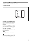
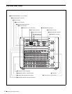
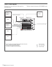
12 Location and Function of Parts
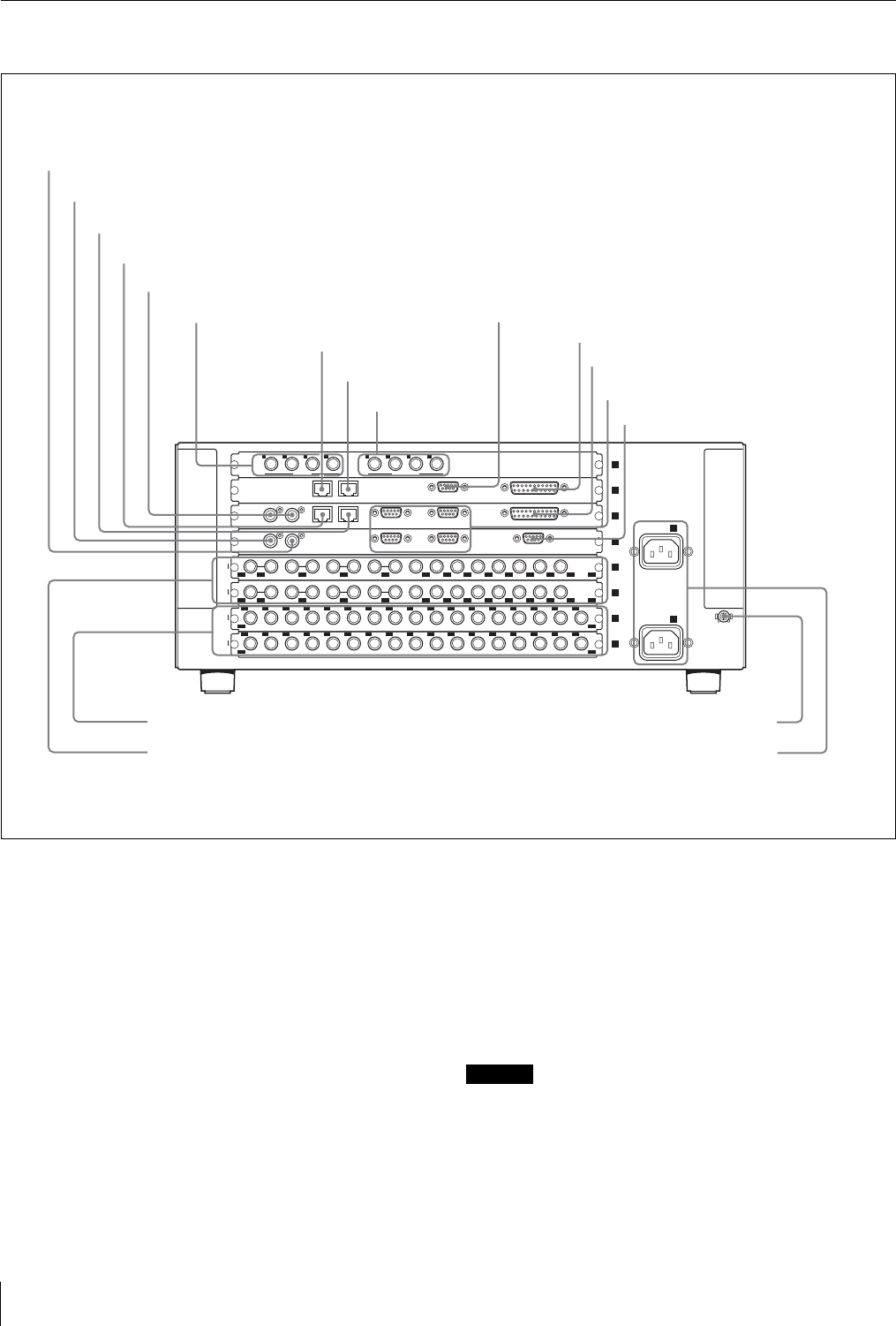
DVS-9000SF Rear Panel
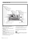
a EXT (extension) connector (BNC type)
Used to expand inputs by connecting devices such as an
HDS-X series routing switcher.
b REF OUT (reference video output) connector
(BNC type)
Output analog sync signals.
c SWITCHER CTRL (Switcher Control) connector
(RJ-45)
Connect to an Ethernet switch*.
The DVS-9000 System is connected in the same way to the
Ethernet switch to form a network for exchange of signals
between the devices.
This network is used primarily to control the various
devices from the center control panel.
* For information about Ethernet switches that can be used in an DVS-9000
system, contact your Sony service representative.
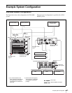
For more information about Ethernet switch connectors,
see “DVS-9000 System Configuration” (page 15).
For detailed information about setting up the Ethernet
switch, refer to the documentation supplied with the
Ethernet switch.
Caution
When using a LAN cable: For safety, do not connect to a
connector for peripheral device wiring that might have
excessive voltage.
DATA CTRL
REMOTE GPI
DATA CTRL
REMOTE 2 REMOTE 1 GPIREF IN
REMOTE 4 REMOTE 3 TERMINAL
REF OUT
EXT
1
2
3
4
SD
SD
1
1
17
IN
2 3 4 5 6 7 8 9 10 11 12 13 14 15 16 17
1
18
34
IN
2 3 4 5 6 7 8 9 10 11 12 13 14 15 16 17
7
8
SD
1 2 3 4 5 7 9 11 126 8 10
1
12
OUT
SD
1 2 3 4 5 7 9 11 126 8 10
OUT
13
24
5
6
A
- AC IN
B
- AC IN
U
EXT IN
123 4 1 2 3 4
MONI OUT
1EXT connector
2REF OUT connector
6DME EXT IN 1 to 4 connectors
3SWITCHER CTRL connector
7DME DATA connector
4SWITCHER DATA connector
8DME CTRL connector
5REF IN connectors
9 DME MONI OUT
1 to 4
connectors
qjPRIMARY INPUTS 1 to 34 connectors
qkOUTPUTS 1 to 24 connectors
qgU terminal
qh-AC IN A, B connectors
qaDME GPI connector
qsSWITCHER GPI connector
qdSWITCHER REMOTE 1 to 4 connectors
qfTERMINAL connector
0DME REMOTE connector