


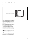
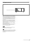


15Example System Configuration
Example System Configuration
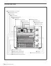
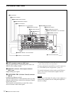
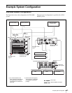
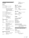
DVS-9000 System Configuration
The figure below shows the configuration of a DVS-9000
system.
The same type of configuration is possible with a DVS-
9000SF system.
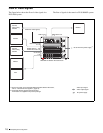
DATA CTRL
REMOTE GPI
DATA CTRL
REMOTE 2 REMOTE 1 GPIREF IN
REMOTE 4 REMOTE 3 TERMINAL
REF OUT
EXT
49
56
OUT SD
SD
SD
SD
SD
SD
SD
1 2 3 4 5 6 7 8
1 2 3 4 5 7 9 11 126 8 10
69
69
80
IN
70 71 72 73 74 75 76 77 78 79 80
1
1
17
IN
2 3 4 5 6 7 8 9 10 11 12 13 14 15 16 17
1
18
34
IN
2 3 4 5 6 7 8 9 10 11 12 13 14 15 16 17
1
35
51
IN
2 3 4 5 6 7 8 9 10 11 12 13 14 15 16 17
1
52
68
IN
2 3 4 5 6 7 8 9 10 11 12 13 14 15 16 17
1
12
OUT
SD
1 2 3 4 5 7 9 11 126 8 10
OUT
SD
1 2 3 4 5 7 9 11 126 8 10
OUT
SD
1 2 3 4 5 7 9 11 126 8 10
OUT
13
24
25
36
37
48
A
1
2
3
4
5
6
7
8
9
10
11
12
13
14
15
16
17
- AC IN
B
- AC IN
C
- AC IN
D
- AC IN
U
EXT IN
123 4 1 2 3 4
MONI OUT
CTRL
REMOTE
SWITCHER DATA
DME
DATA
DME
CTRL
SWITCHER CTRL
SWITCHER
REMOTE
DME
REMOTE
DATA
PERIPH
PERIPH
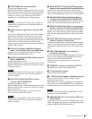
BVE-9100 Editing
Control System
Ethernet switch
a)
Ethernet switch
a)
DVS-9000-C Switcher
Processor Pack
Reference video
signal
b)
Reference video
signal
b)
BKS-R Series
HDS-X Series
Reference
video signal
b)
MKS-8010 System
Control Unit
DCU-8000 Device Control Unit Pack
VTR
DDR
Audio Mixer
a)It is recommended that the
CTRL and DATA LAN networks
be configured by connecting
separate Ethernet switches for
each LAN.
b)Terminate with the supplied
75Ω terminators. Terminators
are supplied in the product
package.
Cross cable
Cable with BNC connectors