


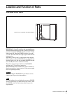
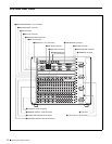
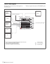
9Location and Function of Parts
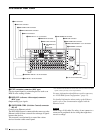
a SWITCHER REMOTE 1 to 4 connectors
(D-sub 9-pin, RS-422A)
Used to control the DVS-9000 AUX bus from external
devices, and to operate the DVS-9000 from editing control
systems such as the BVE-9100.
Specify the types of connected devices on the center
control panel.
b SWITCHER CTRL (Switcher Control) connector
(RJ-45)
Connect to an Ethernet switch*.
The DVS-9000 System is connected in the same way to the
Ethernet switch to form a network for exchange of signals
between the devices.
This network is used primarily to control the various
devices from the center control panel.
* For information about Ethernet switches that can be used in an DVS-9000
system, contact your Sony service representative.
* Ethernet is a trademark of XEROX Corporation.
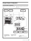
For more information about Ethernet switch connectors,
see “DVS-9000 System Configuration” (page 15).
For detailed information about setting up the Ethernet
switch, refer to the documentation supplied with the
Ethernet switch.
Caution
When using a LAN cable: For safety, do not connect to a
connector for peripheral device wiring that might have
excessive voltage.
c EXT (extension) connector (BNC type)
Used to expand inputs by connecting devices such as an
HDS-X series routing switcher.
d REF OUT (reference video output) connector
(BNC type)
Output analog sync signals.
e SWITCHER DATA connector (RJ-45)
Connect to an Ethernet switch.
The DVS-9000 System is connected in the same way to the
Ethernet switch to form a network for exchange of signals
between the devices.
This network is used primarily for exchange of various
types of data (key frame effects, snapshots, etc.) and still
pictures of frame memory.
Caution
When using a LAN cable: For safety, do not connect to a
connector for peripheral device wiring that might have
excessive voltage.
f REF IN (reference signal input) connectors
(BNC type)
If you wish to synchronize this unit to an external reference
signal, input a black burst signal or analog sync signal. The
two connectors have a loop-through configuration.
Signal input to one connector can be output from the other
connector. If you will not be using the loop-through
output, be sure to terminate the unused connector with the
supplied 75Ω terminator.
g DME EXT IN (Digital Multi Effects External
input) 1 to 4 connectors (BNC type) (BKDS-9470)
Connectors for four serial digital video signal inputs.
Dedicated input for DME external video.
h DME DATA (Digital Multi Effects Data) connector
(RJ-45) (BKDS-9470)
Connect to an Ethernet switch.
The DVS-9000 System is connected in the same way to the
Ethernet switch to form a network for exchange of signals
between the devices.
Caution
When using a LAN cable: For safety, do not connect to a
connector for peripheral device wiring that might have
excessive voltage.
i DME CTRL (Digital Multi Effects Control)
connector (RJ-45) (BKDS-9470)
Connect to an Ethernet switch.
The DVS-9000 System is connected in the same way to the
Ethernet switch to form a network for exchange of signals
between the devices.
This network is used primarily to control the various
devices from the center control panel.
Caution
When using a LAN cable: For safety, do not connect to a
connector for peripheral device wiring that might have
excessive voltage.
j DME MONI OUT (Digital Multi Effects Monitor
Output) 1 to 4 connectors (BNC type) (BKDS-9470)
Connectors for four serial digital video signal outputs.
These connectors allow you to monitor any desired output
signal with the DME signal (video, key, or with graphics).
k DME REMOTE (Digital Multi Effects Remote)
connector (D-sub 9-pin, RS-422A) (BKDS-9470)
When a BKDS-9470 is installed, enables control of DME
operations from remote devices.
l DME GPI (Digital Multi Effects General Purpose
Interface) connector (D-sub 25-pin) (BKDS-9470)
Connect to external devices for input and output of trigger
signals. Up to eight inputs and eight outputs are possible,
with input and output conditions set on the center control
panel.