


62
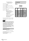
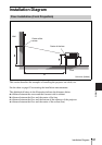
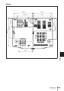
Installation Diagram
a (N) = {(PS × 18.368/0.6299)–35.3} × 1.025
a (M) = {(PS × 22.08003/0.6299)–36.2} × 0.975
b = x–(PS/0.6299 × 3.2)
c = x–(PS/0.6299 × 3.2+32.8)
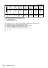
The alphabetical letters in the charts and calculation methods indicate the following.
PS: projected image size measured diagonally (inches)
a: distance between the screen and the foremost side in cabinet
b: distance between the floor and the center of the lens
c: distance between the floor and the adjusters of the projector
x: distance between the floor and the screen (free)
N: minimum
M: maximum
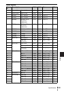
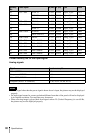
Unit: mm (inches)
PS
30 40 60 80 100 120 150
a
N
860
(33
7
/
8
)
1160
(45
3
/
4
)
1760
(69
3
/
8
)
2360
(93)
2950
(116
1
/
4
)
3550
(139
7
/
8
)
4450
(175
1
/
4
)
M
990
(39)
1330
(52
3
/
8
)
2020
(79
5
/
8
)
2700
(106
3
/
8
)
3380
(133
1
/
8
)
4070
(160
3
/
8
)
5090
(200
1
/
2
)
b
x-152
(x-6)
x-203
(x-8)
x-305
(x-12 )
x-406
(x-16)
x-508
(x-20)
x-610
(x-2
4
)
x-762
(x-30)
c
x-185
(x-7
3
/
8
)
x-236
(x-9
3
/
8
)
x-338
(x-13
3
/
8
)
x-439
(x-17
3
/
8
)
x-541
(x-21
3
/
8
)
x-642
(x-25
3
/
8
)
x-795
(x-31
3
/
8
)