


PFV-SP3100
1-8 (E)
1-7. Matching Connector/Cable
When external cables are connected to the connectors on the PFV-SP3100 rear panel, the hardware listed below (or the
equivalent) must be used.
PFV-SP3100 connector Matching connector/cable
Print on Connector type Connector type Sony Part Number
REMOTE BNC, 75Z BNC, 75Z 1-569-370-12
REF IN A/B Belden 1694 coaxial cable –
STATUS OUT D-sub Mini 15-pin, Female D-sub Mini 15-pin, Male –
1-8. Signal Inputs/Outputs
The input and output signals of the connector on the rear panel are as shown here:
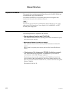
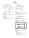
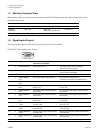
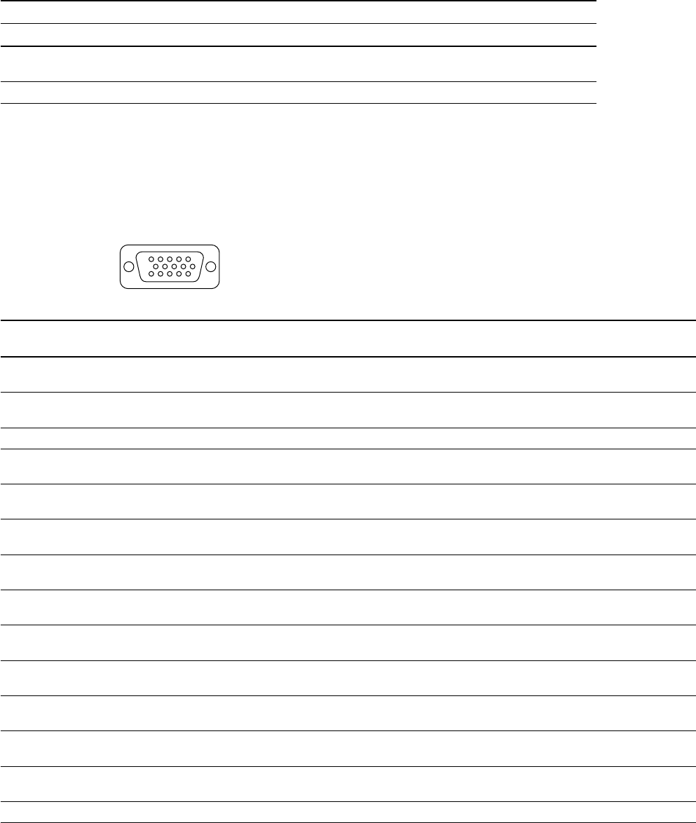
STATUS OUT (D-sub Mini 15-pin, female)
Pin No. I/O Signal Function (All pins are low in level Description
under normal conditions)
1 O PS-A ERROR OUT State of power unit A The output of power unit A is abnormal.
The fan of power unit A stops.
2 O PS-B ERROR OUT State of power unit B The output of power unit B is abnormal.
The fan of power unit B stops.
3 O FAN ERROR OUT State of frame ventilation fan The frame ventilation fan stops.
4 O BOARD ERROR Error status output of optional board Error output from optional board
OUT Overpower consumption from optional board
5 O BOARD WARNING Warning status output of optional board Warning output from optional board
OUT
6 O BOARD ERROR 1 Error status output of board installed in Error output from the optional board installed in
OUT the No.1 slot the No.1 slot.
7 O BOARD ERROR 2 Error status output of board installed in Error output from the optional board installed in
OUT the No.2 slot the No.2 slot.
8 O BOARD ERROR 3 Error status output of board installed in Error output from the optional board installed in
OUT the No.3 slot the No.3 slot.
9 O BOARD ERROR 4 Error status output of board installed in Error output from the optional board installed in
OUT the No.4 slot the No.4 slot.
10 O BOARD WARNING Warning status output of board installed Warning output from the optional board installed
1 OUT in the No.1 slot in the No.1 slot.
11 O BOARD WARNING Warning status output of board installed Warning output from the optional board installed
2 OUT in the No.2 slot in the No.2 slot.
12 O BOARD WARNING Warning status output of board installed Warning output from the optional board installed
3 OUT in the No.3 slot in the No.3 slot.
13 O BOARD WARNING 4 Warning status output of board installed Warning output from the optional board installed
OUT in the No.4 slot in the No.4 slot.
14, 15 – GND
1-7. Matching Connector/Cable
1-8. Signal Inputs/Outputs
51
10 6
15
< External view >
11