


12 (EN)
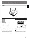
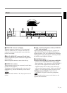
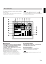
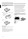
6 VIDEO IN/OUT connectors
VIDEO IN connector (BNC type): Connects to the
composite video output of the video equipment.
VIDEO OUT connector (BNC type): Connects to the
composite video input of a color monitor.
7 S VIDEO IN/OUT connectors
Y IN, C IN connectors (BNC type): Connects to the
Y and C video outputs of the video equipment.
S VIDEO IN/OUT connectors (4-pin, mini-DIN
type): Connects to the S video output or input of
the video equipment.
Note
The S VIDEO IN connector is disconnected when a cable is
connected to the Y/C IN connectors.
8 INPUT A connectors (BNC type)
R/R-Y/P
R, G/Y, B/B-Y/PB, SYNC/HD, VD
connectors: Connect to the outputs of a computer or a
video camera. According to the connected
equipment, the RGB (R, G, B), component (R-Y, G,
B-Y) or HDTV (P
R, Y, PB) signal is selected.
9 Signal interface board attachment part (INPUT
B)
The IFB-40 Signal Interface Board is installed by
default. Other optional signal interface boards can be
attached to this section instead of the IFB-40.
Indicator (red): Lights up when the input of the IFB-
40 is selected.
REMOTE 1 IN connector (14-pin multi): When
connecting two projectors, connect to the REMOTE
1 OUT connector on the IFB-40 installed to another
projector.
REMOTE 1 OUT connector (14-pin multi): Connect
to the REMOTE 1 IN connector on the IFB-40.
MODE selector: Turn the control switch of the
MODE selector to the appropriate position according
to the length of the cable connected to the REMOTE
1 OUT connector.
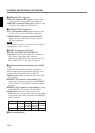
Cable length
Type of cable
Position
!º Rear ventilation hole
Location and Function of Controls
up to 2 m
SIC-M-1
CCQ-2BRS
1
up to 25 m
SIC-M-15
CCQ-25BRS
SIC-M-25
3
up to 10 m
SIC-M-5
CCQ-5BRS
CCQ-10BRS
2
up to 50 m
SIC-M-50
CCQ-50BRS
4